Answered step by step
Verified Expert Solution
Link Copied!

Question

1 Approved Answer

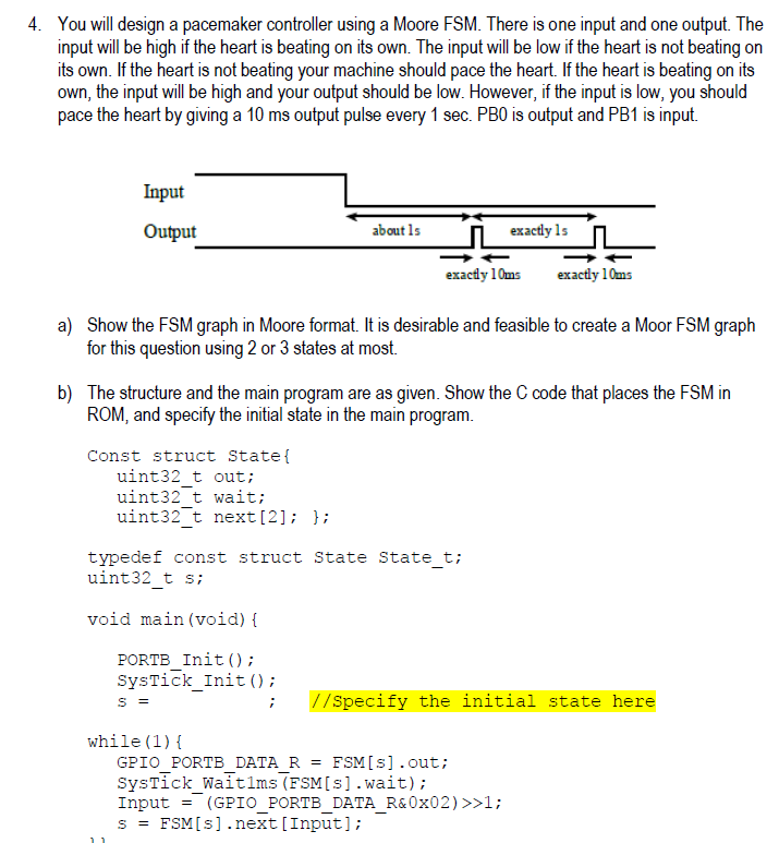
Just Part B please 4. You will design a pacemaker controller using a Moore FSM. There is one input and one output. The input will

Just Part B please

image text in transcribed

4. You will design a pacemaker controller using a Moore FSM. There is one input and one output. The input will be high if the heart is beating on its own. The input will be low if the heart is not beating on its own. If the heart is not beating your machine should pace the heart. If the heart is beating on its own, the input will be high and your output should be low. However, if the input is low, you should pace the heart by giving a 10 ms output pulse every 1 sec. PB0 is output and PB1 is input. Input Output about ls exactly 1s exactly 10ms exactly 10ms a) Show the FSM graph in Moore format. It is desirable and feasible to create a Moor FSM graph for this question using 2 or 3 states at most. b) The structure and the main program are as given. Show the C code that places the FSM in ROM, and specify the initial state in the main program Const struct State uint32 t out uint32 t wait; uint32 t next[21 typedef const struct State State t; uint32 t s; void main (void) t PORTB Init ); SysTick_Inito; //Specify the initial state here while (1) GPIO PORTB DATA R FSMIs] .out; SysTick_Waitlms (FSM[s].wait); Input = (GPIOPORTBDATAR&Ox02) >>1; sFSM[s].next [Input]; - - - 4. You will design a pacemaker controller using a Moore FSM. There is one input and one output. The input will be high if the heart is beating on its own. The input will be low if the heart is not beating on its own. If the heart is not beating your machine should pace the heart. If the heart is beating on its own, the input will be high and your output should be low. However, if the input is low, you should pace the heart by giving a 10 ms output pulse every 1 sec. PB0 is output and PB1 is input. Input Output about ls exactly 1s exactly 10ms exactly 10ms a) Show the FSM graph in Moore format. It is desirable and feasible to create a Moor FSM graph for this question using 2 or 3 states at most. b) The structure and the main program are as given. Show the C code that places the FSM in ROM, and specify the initial state in the main program Const struct State uint32 t out uint32 t wait; uint32 t next[21 typedef const struct State State t; uint32 t s; void main (void) t PORTB Init ); SysTick_Inito; //Specify the initial state here while (1) GPIO PORTB DATA R FSMIs] .out; SysTick_Waitlms (FSM[s].wait); Input = (GPIOPORTBDATAR&Ox02) >>1; sFSM[s].next [Input]

Step by Step Solution

There are 3 Steps involved in it

Step: 1

blur-text-image

Get Instant Access to Expert-Tailored Solutions

See step-by-step solutions with expert insights and AI powered tools for academic success

Step: 2

blur-text-image

Step: 3

blur-text-image

Ace Your Homework with AI

Get the answers you need in no time with our AI-driven, step-by-step assistance

Get Started

Students also viewed these Databases questions

Question

The Nature of Language

Answered: 1 week ago

Question

=+Trainers from headquarters? Local trainers? Independent trainers?

Answered: 1 week ago