Answered step by step
Verified Expert Solution
Question
1 Approved Answer
L A portal frame with fully fixed supports (fig. 1) carries loads applied via purlin points along the length of the roof of the


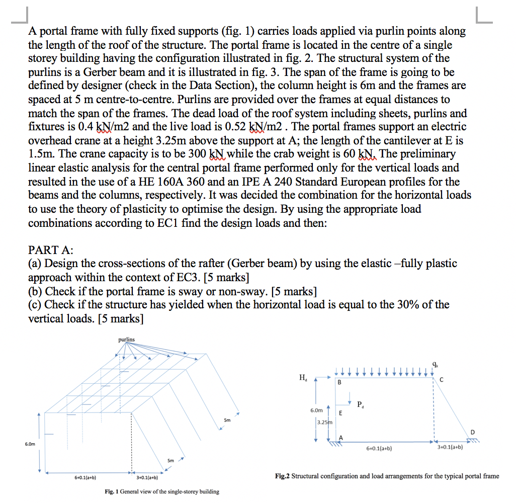
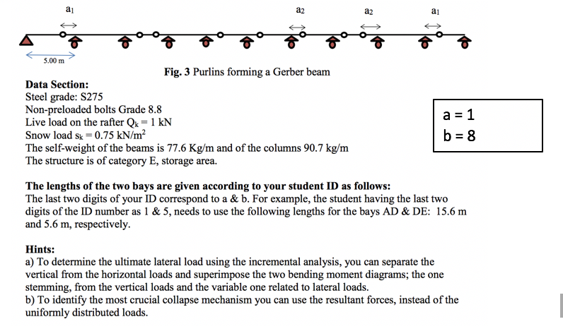
L A portal frame with fully fixed supports (fig. 1) carries loads applied via purlin points along the length of the roof of the structure. The portal frame is located in the centre of a single storey building having the configuration illustrated in fig. 2. The structural system of the purlins is a Gerber beam and it is illustrated in fig. 3. The span of the frame is going to be defined by designer (check in the Data Section), the column height is 6m and the frames are spaced at 5 m centre-to-centre. Purlins are provided over the frames at equal distances to match the span of the frames. The dead load of the roof system including sheets, purlins and fixtures is 0.4 kN/m2 and the live load is 0.52 kN/m2 . The portal frames support an electric overhead crane at a height 3.25m above the support at A; the length of the cantilever at E is 1.5m. The crane capacity is to be 300 KN while the crab weight is 60 kN. The preliminary linear elastic analysis for the central portal frame performed only for the vertical loads and resulted in the use of a HE 160A 360 and an IPE A 240 Standard European profiles for the beams and the columns, respectively. It was decided the combination for the horizontal loads to use the theory of plasticity to optimise the design. By using the appropriate load combinations according to EC1 find the design loads and then: PART A: (a) Design the cross-sections of the rafter (Gerber beam) by using the elastic -fully plastic approach within the context of EC3. [5 marks] (b) Check if the portal frame is sway or non-sway. [5 marks] (c) Check if the structure has yielded when the horizontal load is equal to the 30% of the vertical loads. [5 marks] 6.0m 6+0.1(a+b) purlins 4 3+0.1(a+b) 5m Fig. 1 General view of the single-storey building H 6.0m 3.25m B E P 6+0.1(a+b) 3+0.1(a+b) D M Fig.2 Structural configuration and load arrangements for the typical portal frame 5.00 m a a2 Fig. 3 Purlins forming a Gerber beam Data Section: Steel grade: S275 Non-preloaded bolts Grade 8.8 Live load on the rafter Qk = 1 kN Snow load sk = 0.75 kN/m The self-weight of the beams is 77.6 Kg/m and of the columns 90.7 kg/m The structure is of category E, storage area. a2 al a = 1 b = 8 The lengths of the two bays are given according to your student ID as follows: The last two digits of your ID correspond to a & b. For example, the student having the last two digits of the ID number as 1 & 5, needs to use the following lengths for the bays AD & DE: 15.6 m and 5.6 m, respectively. Hints: a) To determine the ultimate lateral load using the incremental analysis, you can separate the vertical from the horizontal loads and superimpose the two bending moment diagrams; the one stemming, from the vertical loads and the variable one related to lateral loads. b) To identify the most crucial collapse mechanism you can use the resultant forces, instead of the uniformly distributed loads.
Step by Step Solution
★★★★★
3.47 Rating (154 Votes )
There are 3 Steps involved in it
Step: 1

Get Instant Access to Expert-Tailored Solutions
See step-by-step solutions with expert insights and AI powered tools for academic success
Step: 2

Step: 3

Ace Your Homework with AI
Get the answers you need in no time with our AI-driven, step-by-step assistance
Get Started


