Question: Lab 13: Waves & interference Learning Objectives Differentiate between types of waves. Understand how to mathematically describe traveling waves. Understand how to model the propagation
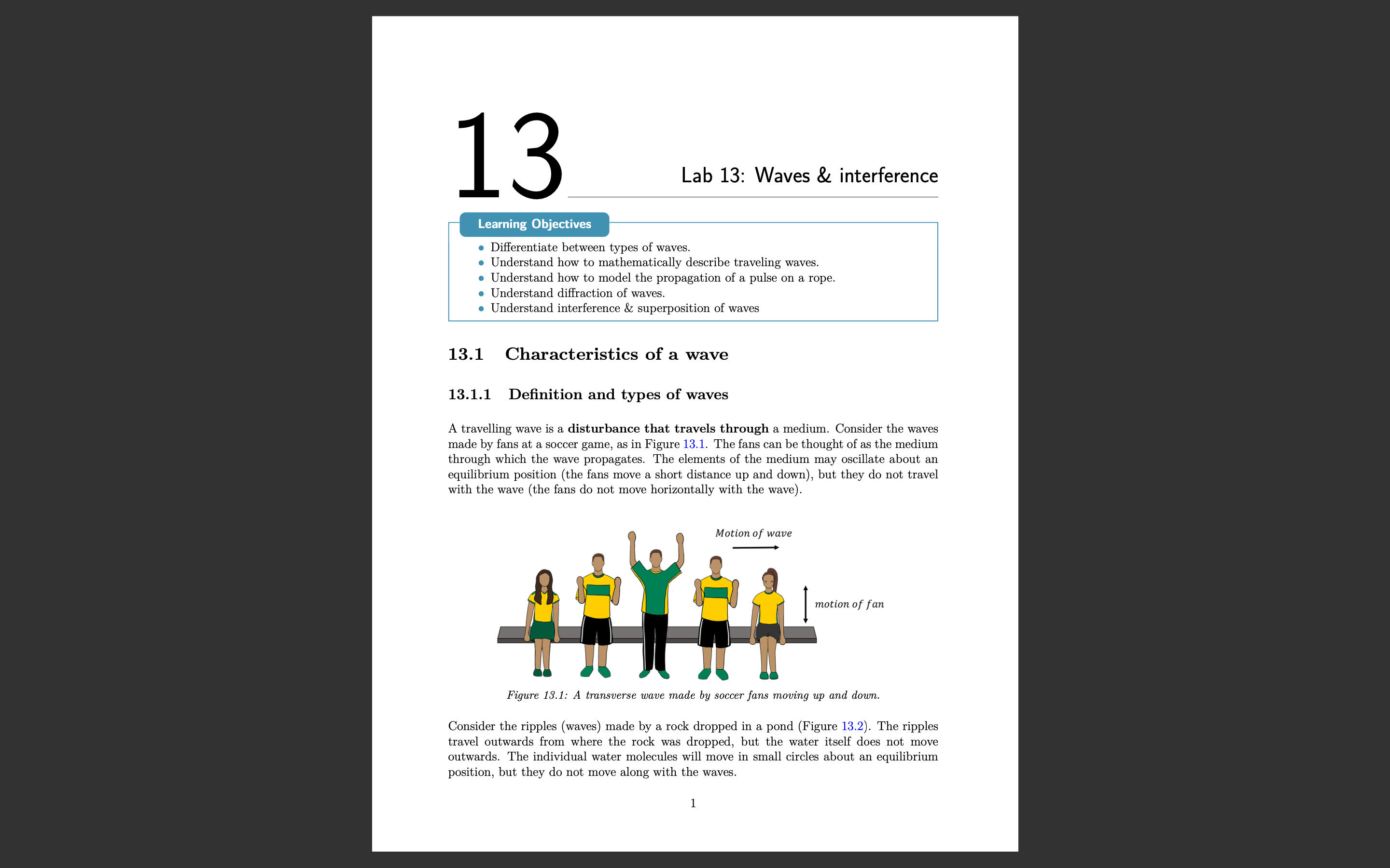
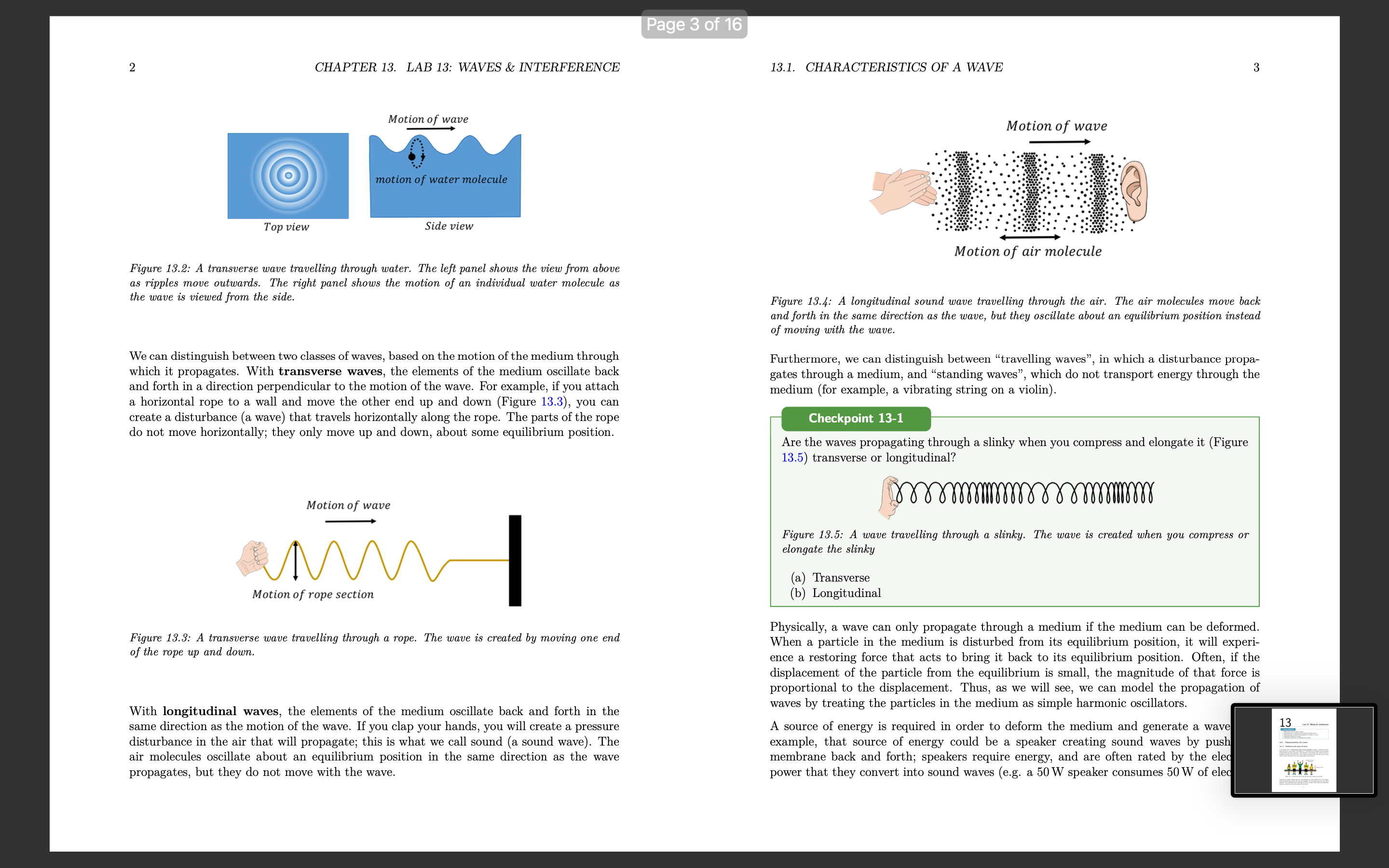
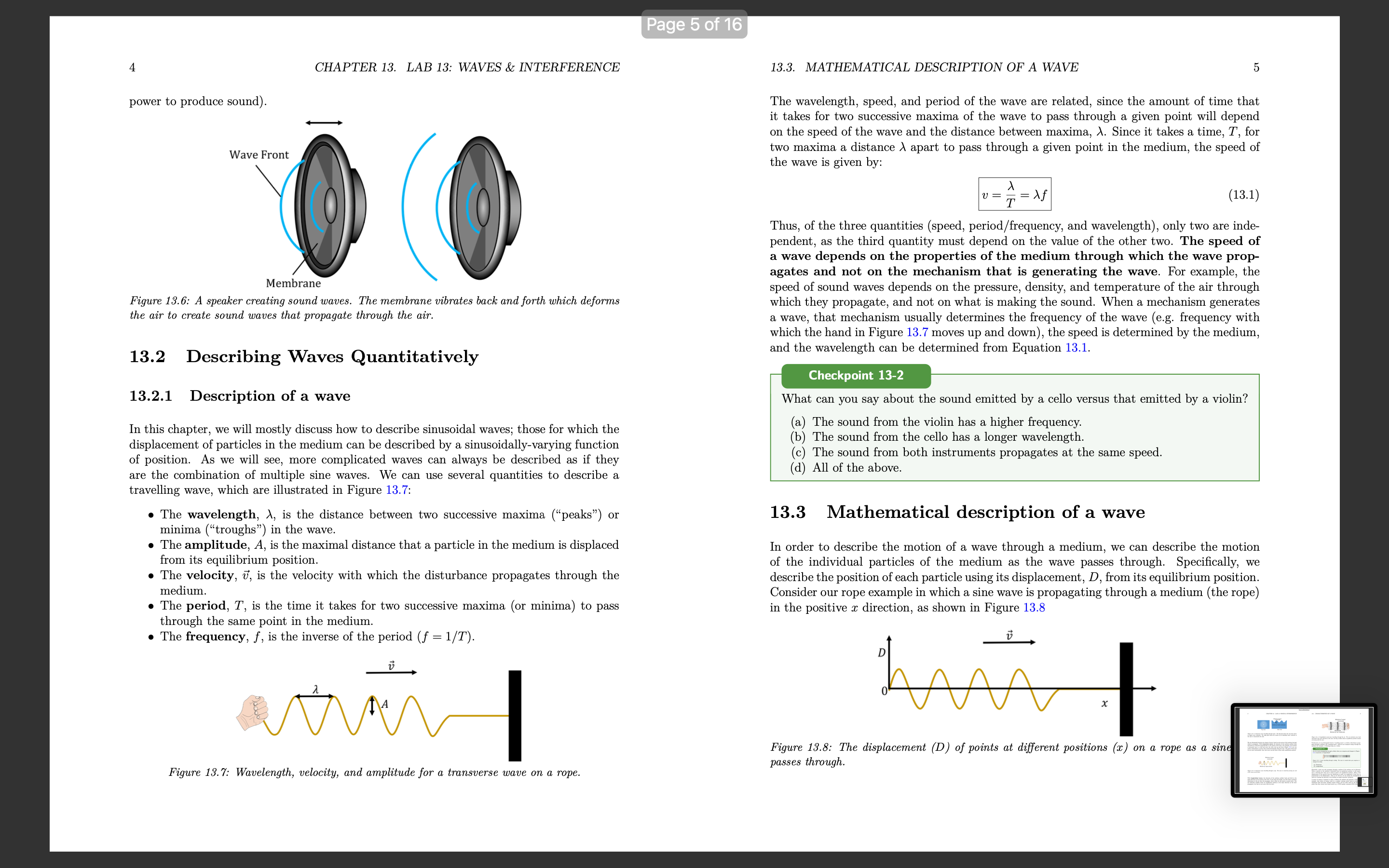
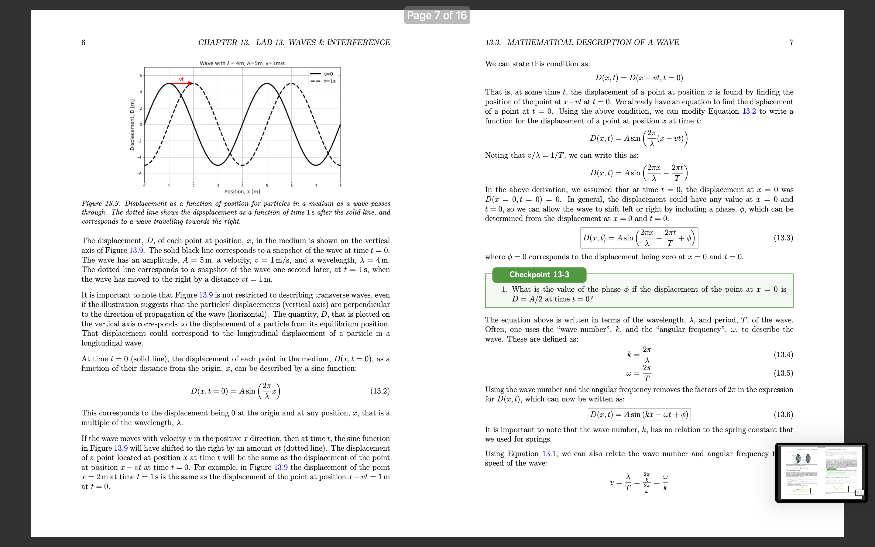
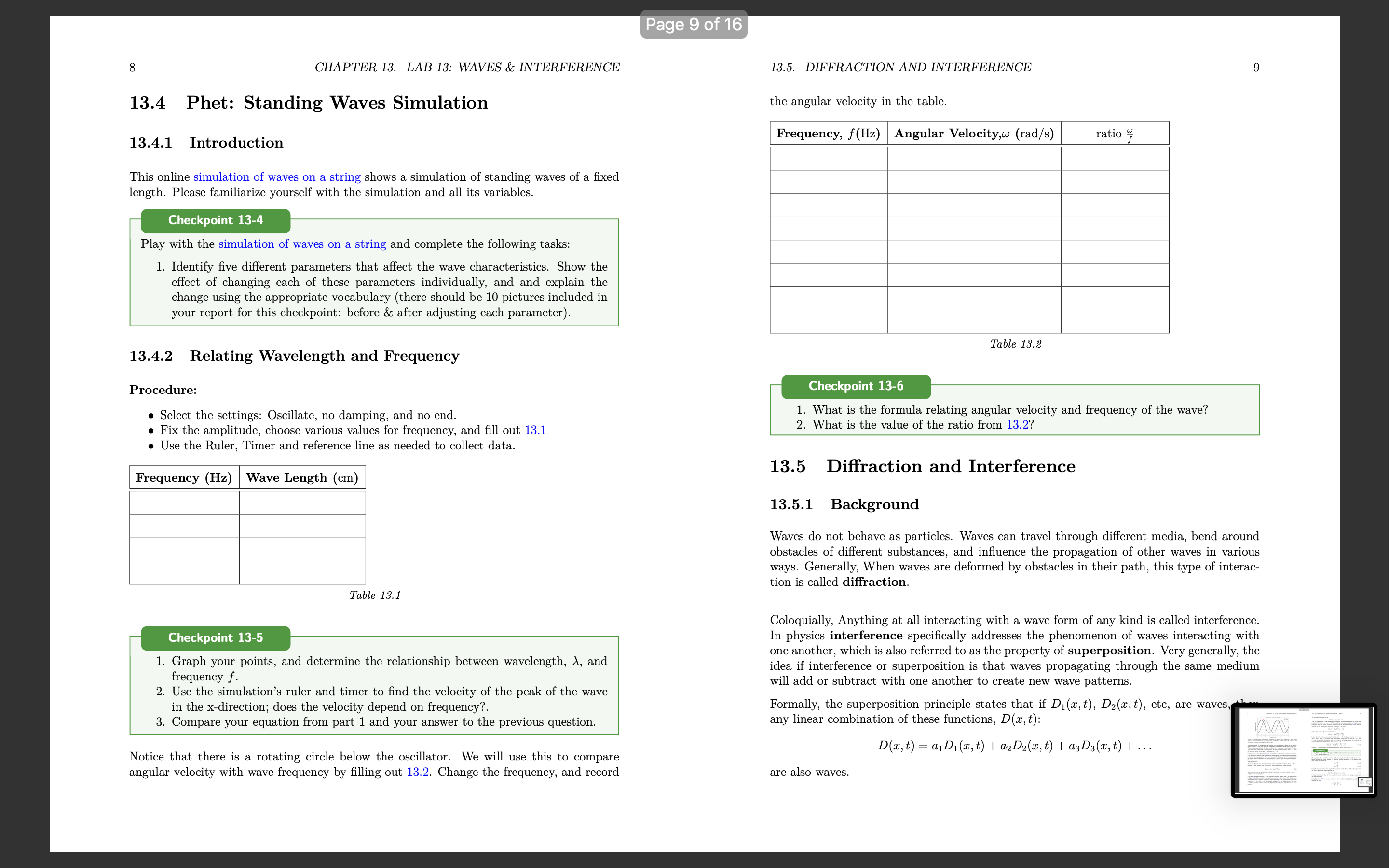
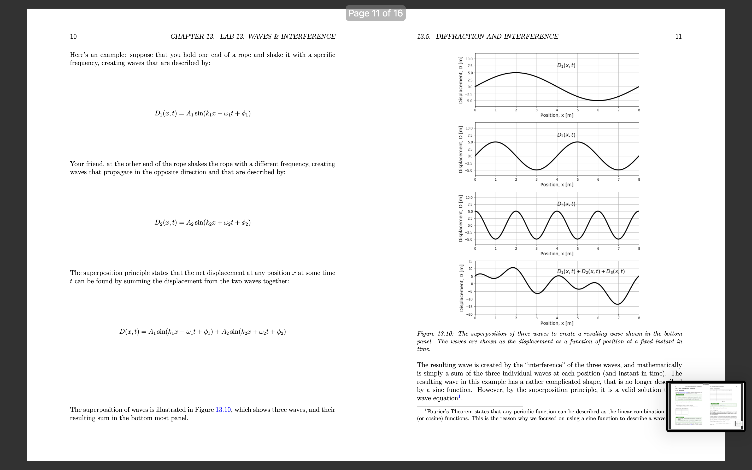
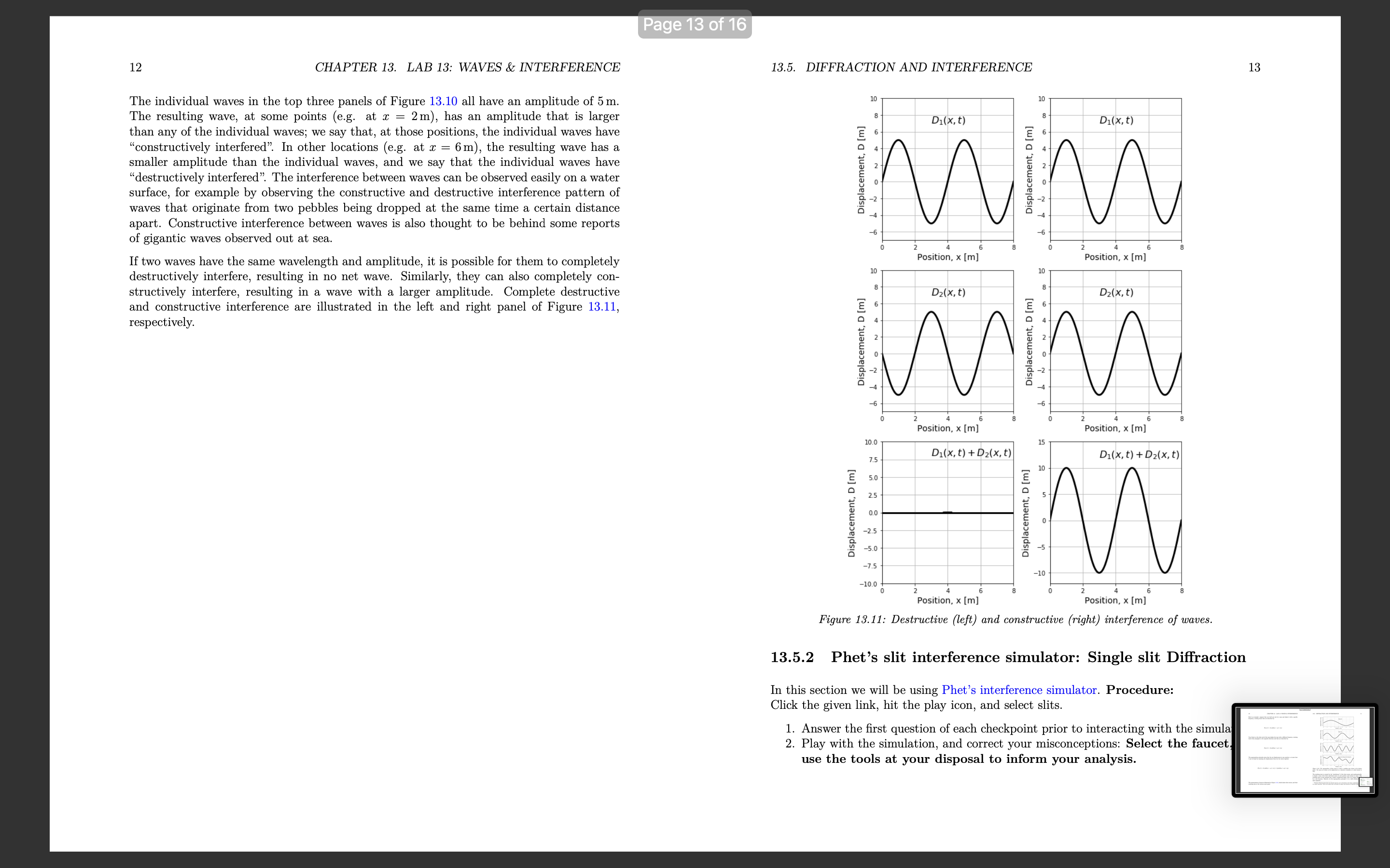
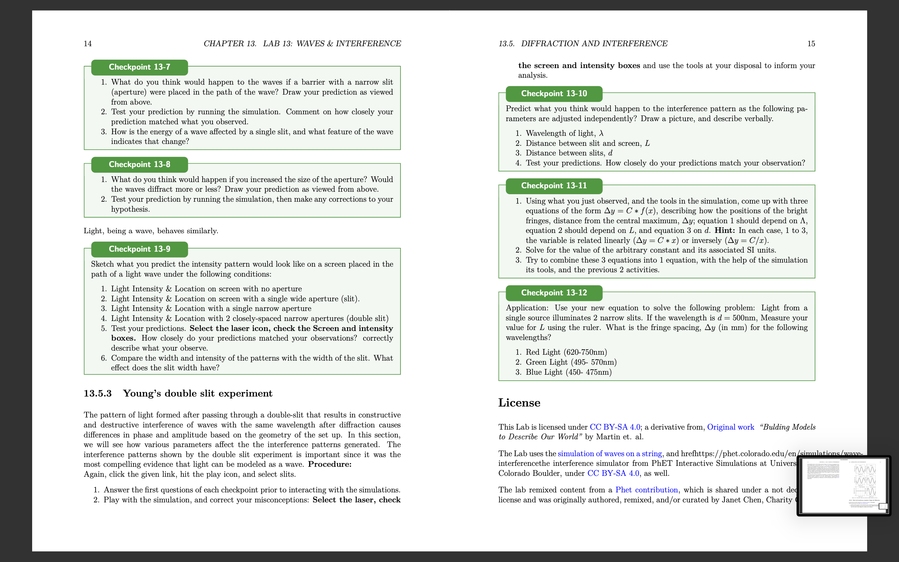
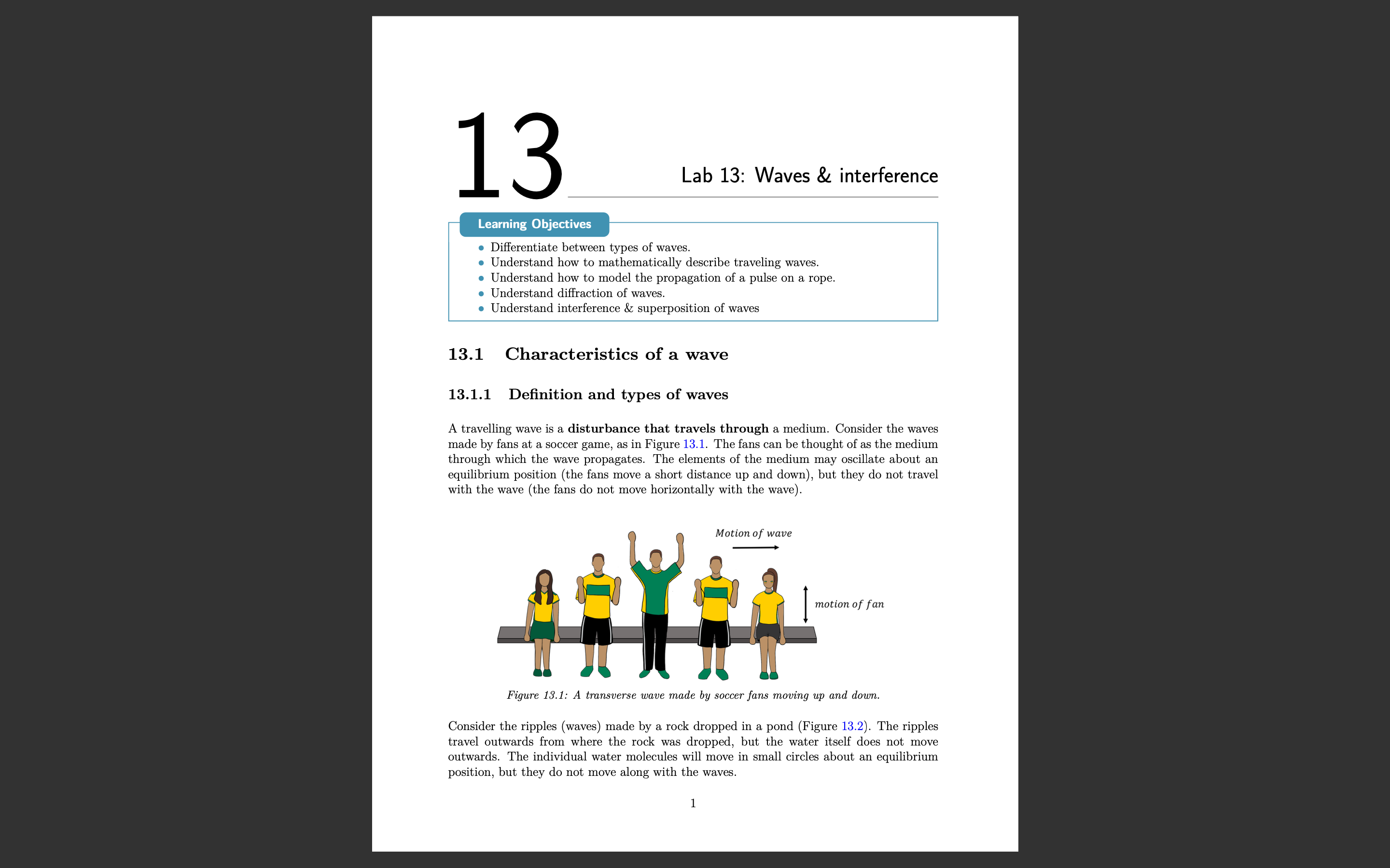
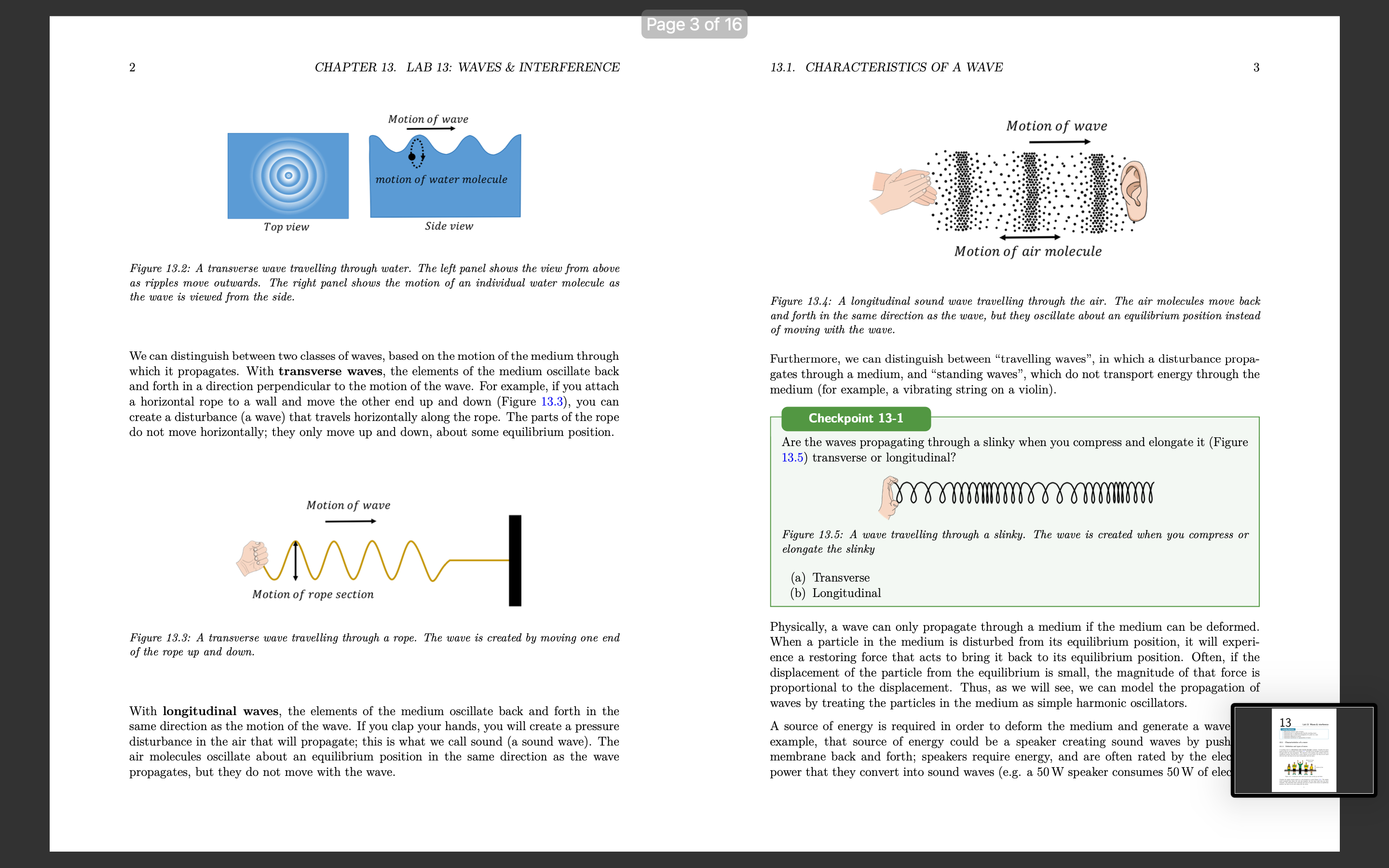
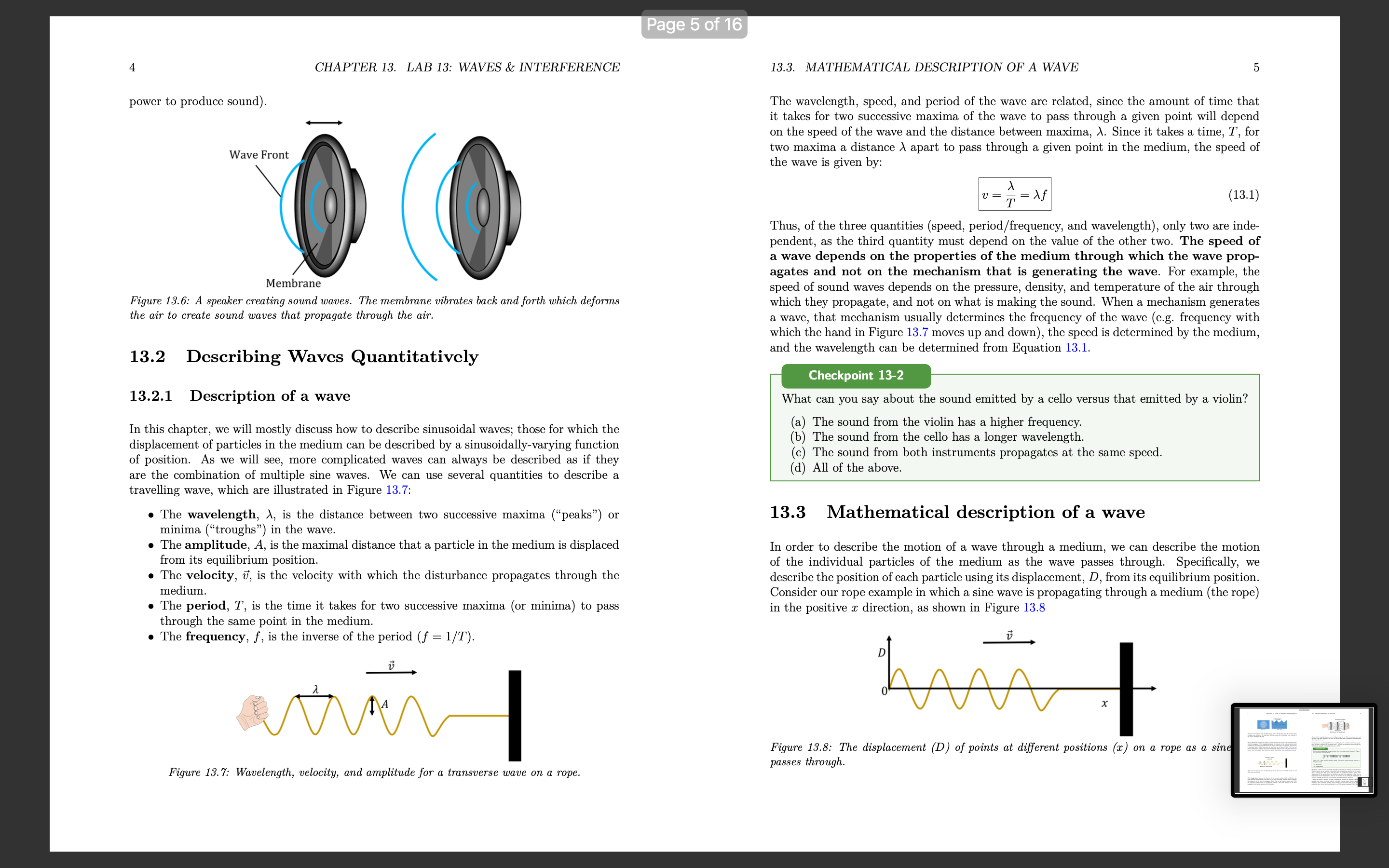
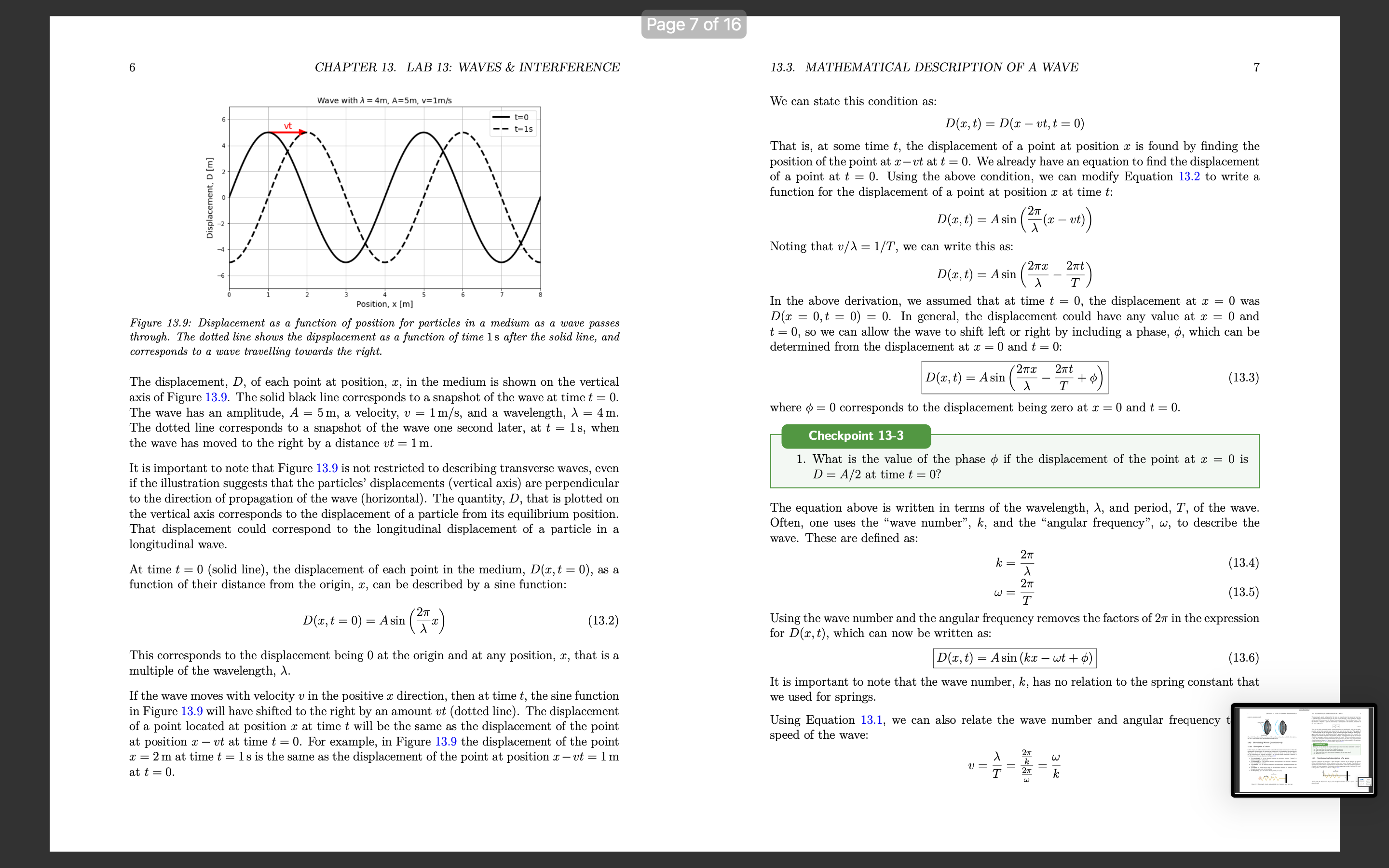
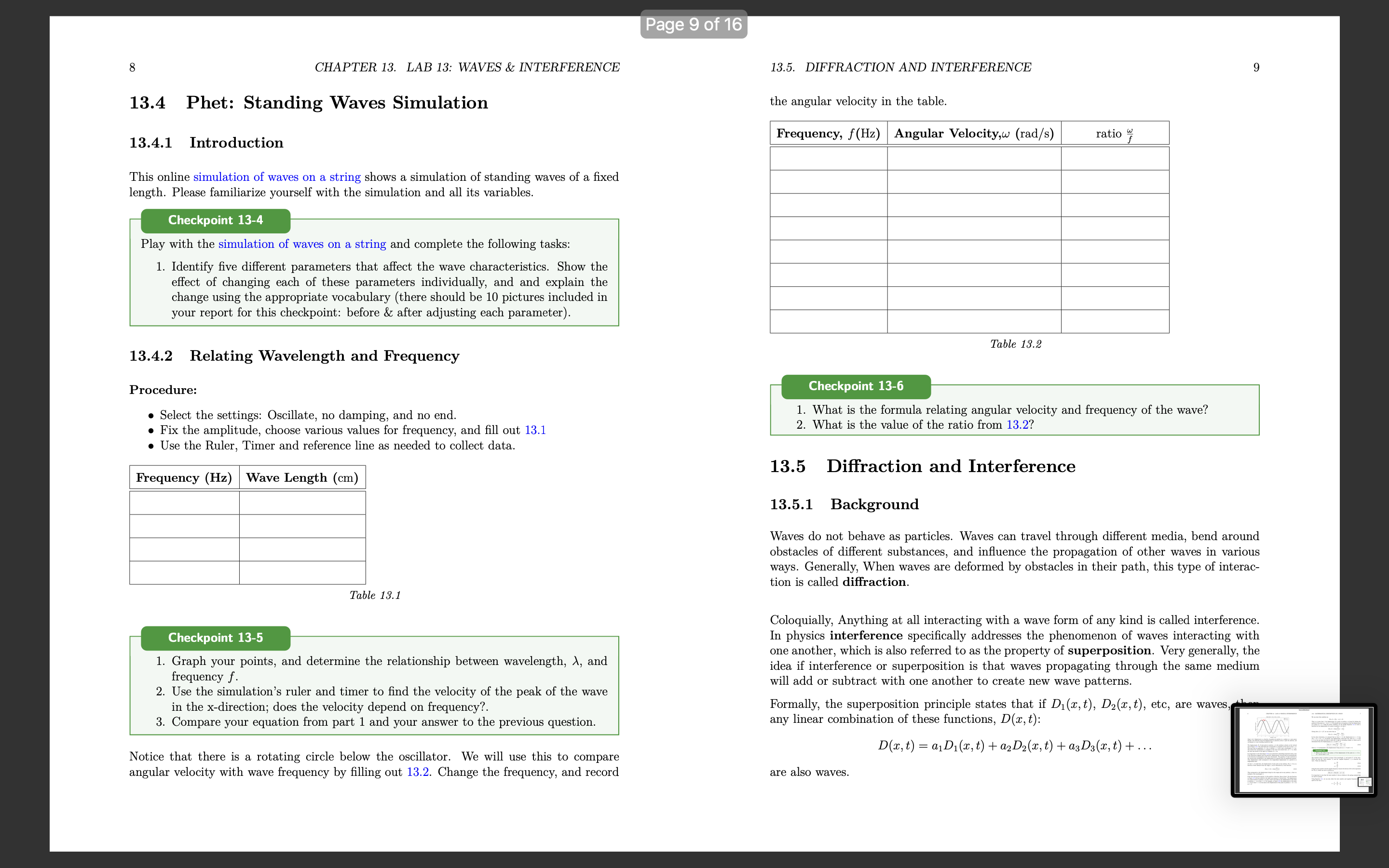
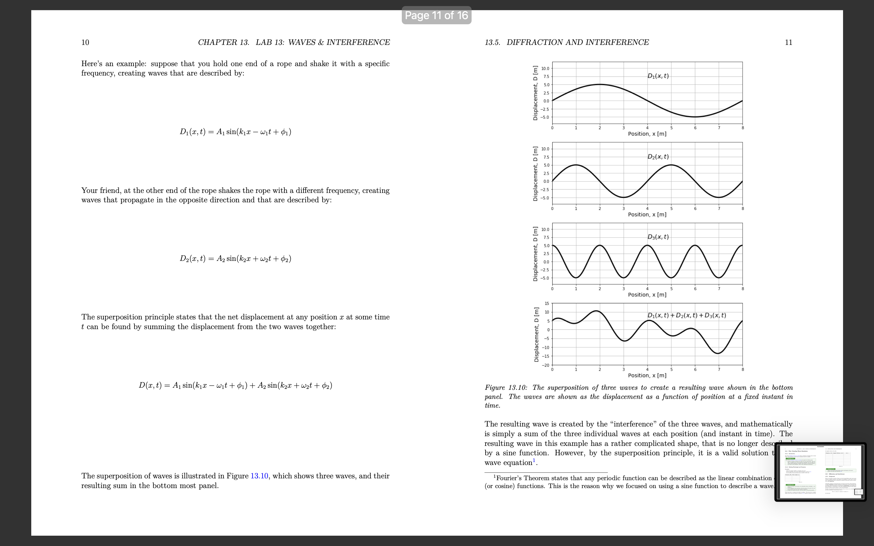
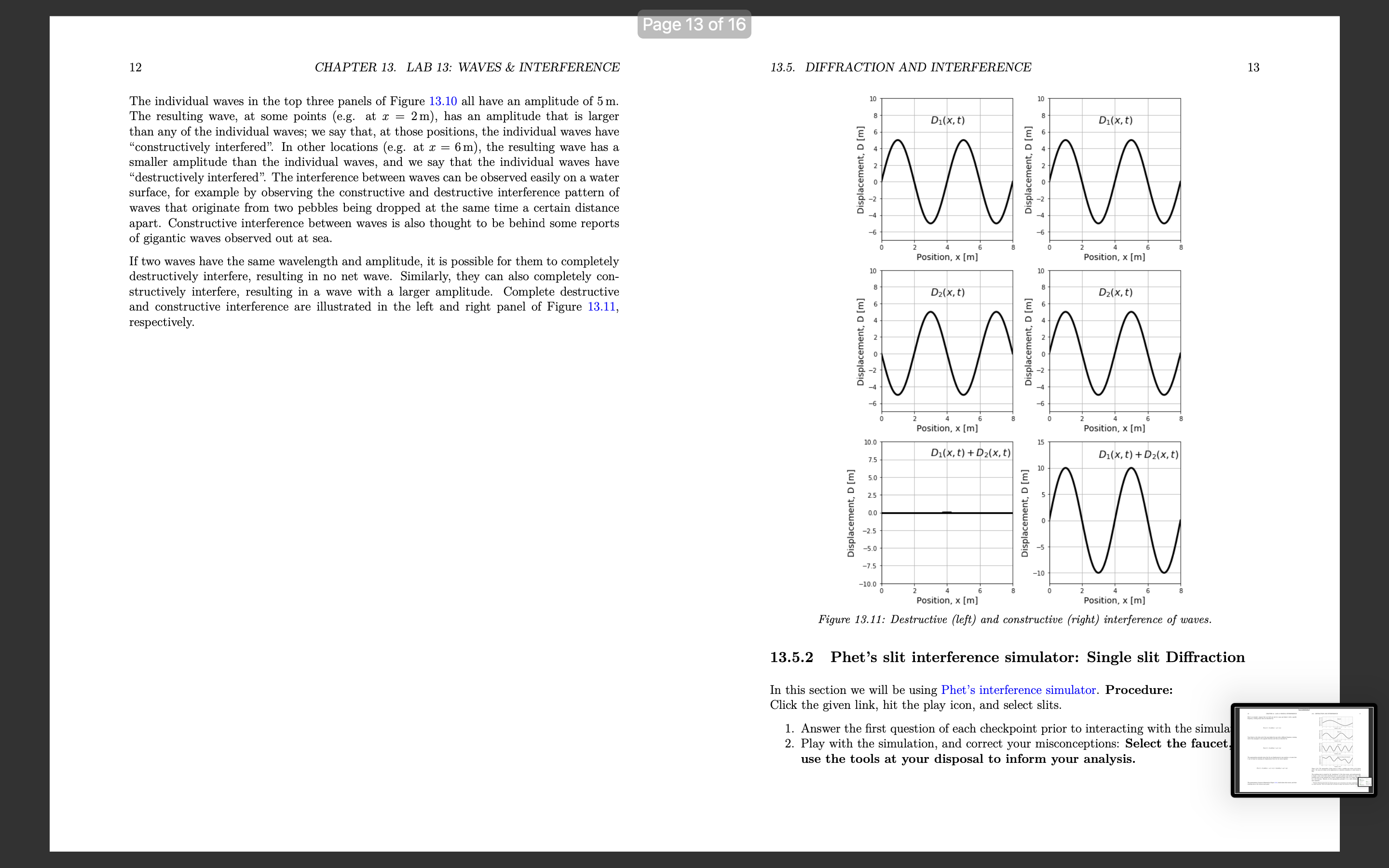
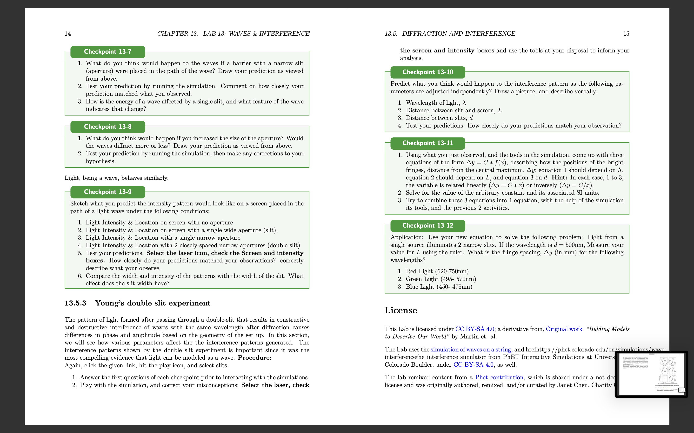
Lab 13: Waves & interference Learning Objectives Differentiate between types of waves. Understand how to mathematically describe traveling waves. Understand how to model the propagation of a pulse on a rope. Understand diffraction of waves. Understand interference & superposition of waves 13.1 Characteristics of a wave 13.1.1 Denition and types of waves A travelling wave is a disturbance that travels through a medium. Consider the waves made by fans at a soccer game, as in Figure 13.1. The fans can be thought of as the medium through which the wave propagates. The elements of the medium may oscillate about an equilibrium position (the fans move a short distance up and down), but they do not travel with the wave (the fans do not move horizontally with the wave) Motion of wave 1 motion of fun Figure 13.1: A transverse wave made by soccer fans moving up and down. Consider the ripples (waves) made by a rock dropped in a pond (Figure 132). The ripples travel outwards from where the rock was dropped, but the water itself docs not move outwards. The individual water molecules will move in small circles about an equilibrium position, but they do not move along with the waves. 1 Page 3 of 16 2 CHAPTER 13. LAB 13: WAVES & INTERFERENCE 13.1. CHARACTERISTICS OF A WAVE 3 Motion of wave Motion of wave motion of water molecule Top view Side view Motion of air molecule Figure 13.2: A transverse wave travelling through water. The left panel shows the view from above as ripples move outwards. The right panel shows the motion of an individual water molecule as the wave is viewed from the side. Figure 13.4: A longitudinal sound wave travelling through the air. The air molecules move back and forth in the same direction as the wave, but they oscillate about an equilibrium position instead of moving with the wave. We can distinguish between two classes of waves, based on the motion of the medium through Furthermore, we can distinguish between "travelling waves", in which a disturbance propa- which it propagates. With transverse waves, the elements of the medium oscillate back gates through a medium, and "standing waves", which do not transport energy through the and forth in a direction perpendicular to the motion of the wave. For example, if you attach medium (for example, a vibrating string on a violin). a horizontal rope to a wall and move the other end up and down (Figure 13.3), you can create a disturbance (a wave) that travels horizontally along the rope. The parts of the rope Checkpoint 13-1 do not move horizontally; they only move up and down, about some equilibrium position. Are the waves propagating through a slinky when you compress and elongate it (Figure 13.5) transverse or longitudinal? Motion of wave Figure 13.5: A wave travelling through a slinky. The wave is created when you compress or M elongate the slink (a) Transverse Motion of rope section b) Longitudinal Physically, a wave can only propagate through a medium if the medium can be deformed. Figure 13.3: A transverse wave travelling through a rope. The wave is created by moving one end When a particle in the medium is disturbed from its equilibrium position, it will experi- of the rope up and down. ence a restoring force that acts to bring it back to its equilibrium position. Often, if the displacement of the particle from the equilibrium is small, the magnitude of that force is proportional to the displacement. Thus, as we will see, we can model the propagation of With longitudinal waves, the elements of the medium oscillate back and forth in the waves by treating the particles in the medium as simple harmonic oscillators. same direction as the motion of the wave. If you clap your hands, you will create a pressure A source of energy is required in order to deform the medium and generate a wave 13.. disturbance in the air that will propagate; this is what we call sound (a sound wave). The example, that source of energy could be a speaker creating sound waves by push air molecules oscillate about an equilibrium position in the same direction as the wave membrane back and forth; speakers require energy, and are often rated by the eled propagates, but they do not move with the wave. power that they convert into sound waves (e.g. a 50 W speaker consumes 50 W of elecCHAPTER 13. LAB 13: WAVES & INTERFERENCE power to produce sound). Wave Front Membrane Figure 15,6: A speaker creating sound waves. The membme m'bmies back and inrth which deforms the air to mate sound waves that propagate through the air, 13.2 Describing Waves Quantitatively 13.2.1 Description of a wave In this chapter, we will mostly discuss how to describe sinusoidal waves; those for which the displacement of particles in the medium can be described by a sinusoidally-varying function of position. As We Will see, more complicated Waves can always be described as if they are the combination of multiple sine waves. We can use several quantities to describe a travelling wave, which are illustrated in Figure 13.7: o The wavelength, A, is the distance between two successive maxima (\"peaks\") or minima (\"troughs\") in the wave. 0 The amplitude, A, is the maximal distance that a particle in the medium is displaced from its equilibrium position, a The velocity, 13', is the velocity with which the disturbance propagates through the medium. 0 The period, T, is the time it takes for two successive maxima (or minima) to pass through the same point in the medium I The frequency, f, is the inverse of the period (f = l/T) _.-._. v A r, Figme 137; Wavelength, velocity, ml amplitude for a tmnsi/arsc win/c on a Topa. 13.3. MATHEMATICAL DESCRIPTION OF A WAVE The wavelength, speed, and period of the wave are related, since the amount of time that it takes for two successive maxima of the wave to pass through a given point will depend on the speed of the Wave and the distance between maxima, A. Since it takes a time, T, for two maxima a distance )r apart to pass through a given point in the medium, the speed of the wave is given by: U : i : /\\f (13.1) Thus, of the three quantities (speed, period/frequency, and wavelength), only two are inde pendent, as the third quantity must depend on the value of the other two. The speed of a wave depends on the properties of the medium through which the wave prop- agates and not on the mechanism that is generating the wave. For example, the speed of sound waves depends on the pressure, density, and temperature of the air through which they propagate, and not on what is making the sound. When a mechanism generates a wave, that mechanism usually determines the frequency of the wave (e.g. frequency with which the hand in Figure 13.7 moves up and down), the speed is determined by the medium, and the wavelength can be determined from Equation 13.1. What can you say about the sound emitted by a cello Versus that emitted by a violin? (a) The sound from the violin has a higher requency. (b) The sound from the cello has a longer wavelength. (c) The sound from both instruments propagates at the same speed. (d) All of the above. 13.3 Mathematical description of a wave In order to describe the motion of a wave through a medium, we can describe the motion of the individual particles of the medium as the wave passes through. Specically, we describe the position of each particle using its displacement, D, from its equilibrium position. Consider our rope example in which a sine wave is propagating through a medium (the rope) in the positive a: direction, as shown in Figure 13.8 _'7_. D 0 X thm 13.8.- The displacement (D) 0/ points at diemnt positions (p) on a mp2 as a 5m. passes through. CHAPTER 13. LAB 13: WAVES & INTERFERENCE Wave mm A = 4m, A=5m, v=lmls Displacement, u [m] Posmon, x [ml Figune 13,9.- Displacement as a function of position for particles in a medium as a wave passes through. The dotted line shows [he dipsplaocmcnt as a function of time Is aim the solid line, and corresponds ta a wave tmeumg tun/mas the right. The displacement, D, of each point at position, I, in the medium is shown on the Vertical axis of Figure 13.9. The solid black line corresponds to a snapshot of the wave at time t : 0. The Wave has an amplitude, A : 5m, a velocity, v : 1 m/s, and a wavelength, A : 4m. The dotted line corresponds to a snapshot of the wave one second later, at t = ls, when the wave has moved to the right by a distance at = 1m. It is important to note that Figure 13.9 is not restricted to describing transverse waves, even if the illustration suggests that the particles' displacements (vertical axis) are perpendicular to the direction of propagation of the wave (horizontal). The quantity, D, that is plotted on the vertical axis corresponds to the displacement of a particle from its equilibrium position. That displacement could correspond to the longitudinal displacement of a particle in a longitudinal Wave. At time t = 0 (solid line), the displacement of each point in the medium, D(z,t = 0), as a function of their distance from the origin, 1, can be described by a sine function: 2 0m: : o) : Asin (TH) (13.2) This corresponds to the displacement being 0 at the origin and at any position, I, that is a multiple of the wavelength, A. If the wave moves with velocity 11 in the positive 1' direction, then at time t, the sine function in Figure 13.9 will have shifted to the right by an amount vt (dotted line). The displacement of a point located at position as at time It Will be the same as the displacement of the point at position I at at time t = 0. For example, in Figure 13.9 the displacement of the point z : 2 m at time t : 1 s is the same as the displacement of the point at position I 7 ut : 1 m at t : 0. 13.3. MATHEMATICAL DESCRIPTION OF A WAVE We can state this condition as: D(I,t) : D(I 71113,! : 0) That is, at some time t, the displacement of a point at position It is found by nding the position of the point at zvt at t = 0. We already have an equation to nd the displacement of a point at t = 0. Using the above condition, we can modify Equation 1312 to write a function for the displacement of a point at position 1' at time t: D(:r, t) : Asin (277%: 7 1113)) Noting that v/A : 1/T, we can write this as: 21m: 21rt _ A ' i _ i D(I,t) Sln( /\\ T ) In the above derimtion, We assumed that at time t = 0, the displacement at z = 0 was D(1 = 0,t = 0) = 0. In general, the displacement could have any value at z = 0 and t : 0, so we can allow the wave to shift left or right by including a phase, , which can be determined from the displacement at a: : 0 and t : 0: (13.3) D(z,t) : Asin (2% 7 % + a) where a : 0 corresponds to the displacement being zero at 1' : 0 and t : 0. Checkpo t 13-3 1. What is the value of the phase a if the displacement of the point at a: : 0 is D: A/2 at timet= 07 The equation above is written in terms of the wavelength, A, and period, T, of the wave. Often, one uses the \"wave number\CHAPTER 13. LAB 13: WAVES & INTERFERENCE 13.4 Phet: Standing Waves Simulation 13.4.1 Introduction This online simulation of waves on a string shows a simulation of standing waves of a xed length. Please familiarize yourself with the simulation and all its Variables. Checkpoint 13-4 Play with the simulation of waves on a string and complete the following tasks: 1. Identify five different parameters that affect the Wave characteristics. Show the effect of changing each of these parameters individually, and and explain the change using the appropriate vocabulary (there should be 10 pictures included in your report for this checkpoint: before EL after adjusting each parameter). 13.4.2 Relating Wavelength and Frequency Procedure: u Select the settings: Oscillate, no damping, and no end. 0 Fix the amplitude, choose Various values for frequency, and fill out 131 I Use the Ruler, Timer and reference line as needed to collect data. Frequency (Hz) Wave Length (cm) Table 13.1 Checkpoint 135 1. Graph your points, and determine the relationship between wavelength, A, and frequency f. 2. Use the simulations ruler and timer to nd the velocity of the peak of the Wave in the xdirection; does the velocity depend on frequency? 3. Compare your equation from part 1 and your answer to the previous question. Notice that there is a rotating circle below the oscillator. We will use this to compare angular velocity with wave frequency by lling out 13.2. Change the frequency, and record 13.5. DIFFRACTION AND INTERFERENCE the angular velocity in the table. Hequency, f (Hz) Angular Velocity,w (rad/s) Table 13.2 Checkpn t 13 1. What is the formula relating angular velocity and frequency of the wave'.7 2. What is the value of the ratio from 13.27 13.5 Diffraction and Interference 13.5.1 Background Waves do not behave as particles. Waves can travel through different media, bend around obstacles of different substances, and inuence the propagation of other waves in various ways. Generally, When Waves are deformed by obstacles in their path, this type of interac- tion is called diffraction. Coloquially, Anything at all interacting with a Wave form of any kind is called interference. In physics interference specically addresses the phenomenon of waves interacting with one another, which is also referred to as the property of superposition. Very generally, the idea if interference or superposition is that waves propagating through the same medium will add or subtract with one another to create new wave patterns. Formally, the superposition principle states that if 01(1, t), Dg(z,t), etc, are waves, any linear combination of these functions, D(z,t): D(m,t) = a1D1(z, t) + agD2(ac, t) + a3D3(ac, t) + . .. are also Waves. 10 CHAPTER 13. LAB 13: WAVES & INTERFERENCE Here's an example: suppose that you hold one end of a rope and shake it with a specic frequency, creating waves that are described by: D](z,t) : A] sin(k]z 7 out + $1) Your friend, at the other end of the rope shakes the rope with a different frequency, creating waves that propagate in the opposite direction and that are described by: D,(e,t) = A2 sin(k21 + wit + in) The superposition principle states that the net displacement at any position 1 at some time t can be found by summing the displacement from the two waves together: D(a:, t) : A1 sin(le,z 7 int + at.) + A2 sin(k;1 + wpt + in) The superposition of waves is illustrated in Figure 13.10, which shows three waves, and their resulting sum in the bottom rnost panel. 13.5. DIFFRACTION AND INTERFERENCE Displacement, D [m] z o s Fosltmn, x [m] D2(x, t) Displacement, D [iii] x e 5 Poslllon, x [iii] Daix, I) E n e n E n E s a I e s Posltlon, x [m] Di(x, II + 02(X, t) + D2(x, t) Displacement, D [m] Position, x [m] Figure 15.10.- The superposition of three waves to crmtc a iesuzting mm shown in the bottom panel. The waves are shown as the displacement a5 a funetien 0/ position at a xed instant in time. The resulting wave is created by the \"interference\" of the three waves, and mathematically is simply a sum of the three individual waves at each position (and instant in time). The resulting wave in this example has a rather complicated shape, that is no longer des- ' by a sine function. However, by the superposition principle, it is a valid solution i wave equationl. lFourier's Theorem states that any periodic function can be described as the linear combination (or cosine) functions. This is the reason why we focused on using a sine tunetion to describe is wave 12 CHAPTER 13. LAB 13: WAVES & INTERFERENCE The individual waves in the top three panels of Figure 13.10 all have an amplitude of 5m. The resulting wave, at some points (eg. at a: : 2m), has an amplitude that is larger than any of the individual waves; we say that, at those positions, the individual Waves have \"constructively interfered'l In other locations (eg at z = 6m), the resulting Vimve has a smaller amplitude than the individual waves, and we say that the individual waves have \"destructively interfered\". The interference between waves can be observed easily on a water surface, for example by observing the constructive and destructive interference pattern of waves that originate from two pebbles being dropped at the same time a certain distance apart. Constructive interference between waves is also thought to be behind some reports of gigantic waves observed out at sea. If two waves have the same Wavelength and amplitude, it is possible for them to completely destructively interfere, resulting in no net wave. Similarly, they can also completely con- structively interfere, resulting in a wave with a larger amplitude Complete destructive and constructive interference are illustrated in the left and right panel of Figure 13.11, respectively. 13.5. DIFFRACTION AND INTERFERENCE Displacement, o [m] Displacement, D [ml 1 . s 2 a a VDSIllcn, x [m] Position, x [m] Dzlx. fl D2(Xi 1) Displacemenr, o [m] Displacement. n [ml 2 e s 2 a 5 Position. x [m] Position, x [m] Dilx, ti +D2(X, t) D.(x, r) + 021ml) Displacement o [m] Displacement. 0 [ml z a s 2 A 6 Position. x [ml Position, x [ml Figure 15.11.- Denruen're (left) and eonslrnen're (right) interference of waves. 13.5.2 Phet's slit interference simulator: Single slit Di'raction In this section we will be using Phet's interference simulator. Procedure: Click the given link, hit the play icon, and select slits. 1. Answer the first question of each checkpoint prior to interacting with the simul 21 Play with the simulation, and correct your misconceptions: Select the faucet use the tools at your disposal to inform your analysis. CHAPTER 13. LAB 13: WAVES & INTERFERENCE Checkpoint 13-1 1. What do you think would happen to the waves if a barrier with a narrow slit (aperture) were placed in the path of the wave? Draw your prediction as viewed from above. 2. Test your prediction by running the simulation. Comment on how closely your prediction matched what you observed. 3. How is the energy of a wave affected by a single slit, and what feature of the wave indicates that change? Checkpoint 13-8 1. What do you think would happen if you increased the size of the aperture? Would the waves diract more or less? Draw your prediction as viewed from above. 2. Test your prediction by running the simulation, then make any corrections to your hypothesis. Light, being a wave, behaves similarly. Checkpoint 13-9 Sketch what you predict the intensity pattern would look like on a screen placed in the path of a light wave under the following conditions: 1. Light Intensity & Location on screen with no aperture . Light Intensity 8L Location on screen with a single wide aperture (slit). . Light Intensity & Location with a single narrow aperture . Light Intensity & Location with 2 closely-spaced narrow apertures (double slit) . Test your predictions. Select the laser icon, check the Screen and intensity boxes. How closely do your predictions matched your observations? correctly describe what your observe. . Compare the width and intensity of the patterns with the width of the slit. What effect does the slit width have? 13.5.3 Young's double slit experiment The pattern of light formed after passing through a double-slit that results in constructive and destructive interference of waves with the same wavelength after diffraction causes differences in phase and amplitude based on the geometry of the set up. In this section, we will see how various parameters affect the the interference patterns generated. The interference patterns shown by the double slit experiment is important since it was the most compelling evidence that light can be modeled as a wave. Procedure: Again, click the given link, hit the play icon, and select slits. 1. Answer the rst questions of each checkpoint prior to interacting with the simulations. 2. Play with the simulation, and correct your misconceptions: Select the laser, check 13.5. DIFFRACTION AND INTERFERENCE 15 the screen and intensity boxes and use the tools at your disposal to inform your analysis. Checkpoint 13-10 Predict what you think would happen to the interference pattern as the following pa rameters are adjusted independently? Draw a picture, and describe verbally. 1. Wavelength of light, A 2. Distance between slit and screen, L 3. Distance between slits, d 4, Test your predictions. How closely do your predictions match your obserwtion'.I Checkpoint 13-11 1, Using what you just observed, and the tools in the simulation, come up with three equations of the form Ag = C s f (c), describing how the positions of the bright fringes, distance from the central maximum, Ay; equation 1 should depend on A, equation 2 should depend on L, and equation 3 on d. Hint: In each case, 1 to 3, the variable is related linearly (Ag : C 4. z) or inversely (Ay : C/z). , Solve for the Wlue of the arbitrary constant and its associated SI units. . Try to combine these 3 equations into 1 equation, with the help of the simulation its tools, and the previous 2 activities Checkpoint 13-12 Application: Use your new equation to solve the following problem: Light from a single source illuminates 2 narrow slits. If the wavelength is d : 500nm, Measure your value for L using the ruler. What is the fringe spacing, Ag (in mm) for the following wavelengths? 1. Red Light (620750nm) 2. Green Light (495- 570nm) 3, Blue Light (450- 475nm) License This Lab is licensed under CC BYSA 4.0; a derivative from, Original work \"Balding Models to Describe Our World\" by Martin et. al. The Lab uses the simulation of waves on a string, and hrelhttps: / / phet.colorado.edu/ en interferencethe interference simulator from PhET Interactive Simulations at Univer Colorado Boulder, under CC BYSA 4.0, as well. The lab remixed content from a Phet contribution, which is shared under a not de: license and was originally authored, remixed, and/or curated by Janet Chen, Charity
Step by Step Solution
There are 3 Steps involved in it

Get step-by-step solutions from verified subject matter experts


