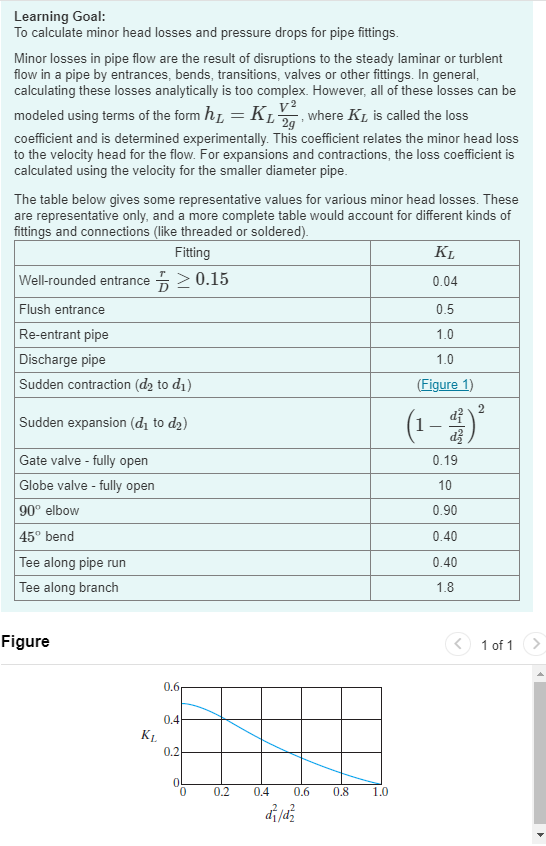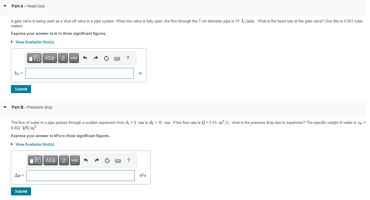


Learning Goal: To calculate minor head losses and pressure drops for pipe fittings. Minor losses in pipe flow are the result of disruptions to the steady laminar or turblent flow in a pipe by entrances, bends, transitions, valves or other fittings. In general, calculating these losses analytically is too complex. However, all of these losses can be modeled using terms of the form hL=KL2gV2, where KL is called the loss coefficient and is determined experimentally. This coefficient relates the minor head loss to the velocity head for the flow. For expansions and contractions, the loss coefficient is calculated using the velocity for the smaller diameter pipe. The table below gives some representative values for various minor head losses. These are representative only, and a more complete table would account for different kinds of fittinqs and connections (like threaded or soldered). Figure 1 of 1 meters. Express your answer in m to three significant figures. hL= m Part B - Pressure drop 9.802kN/m3 Express your answer in kPa to three significant figures. the loss coefficient for the valve? The specific weight of water is w=9.802kN/m3. Express your answer to three significant figures. Learning Goal: To calculate minor head losses and pressure drops for pipe fittings. Minor losses in pipe flow are the result of disruptions to the steady laminar or turblent flow in a pipe by entrances, bends, transitions, valves or other fittings. In general, calculating these losses analytically is too complex. However, all of these losses can be modeled using terms of the form hL=KL2gV2, where KL is called the loss coefficient and is determined experimentally. This coefficient relates the minor head loss to the velocity head for the flow. For expansions and contractions, the loss coefficient is calculated using the velocity for the smaller diameter pipe. The table below gives some representative values for various minor head losses. These are representative only, and a more complete table would account for different kinds of fittinqs and connections (like threaded or soldered). Figure 1 of 1 meters. Express your answer in m to three significant figures. hL= m Part B - Pressure drop 9.802kN/m3 Express your answer in kPa to three significant figures. the loss coefficient for the valve? The specific weight of water is w=9.802kN/m3. Express your answer to three significant figures


