Question: level from three to tuo. Table 1 sbows the relationship between the sense input signals and encoder output signals and L. 1. (10 pont) Complete


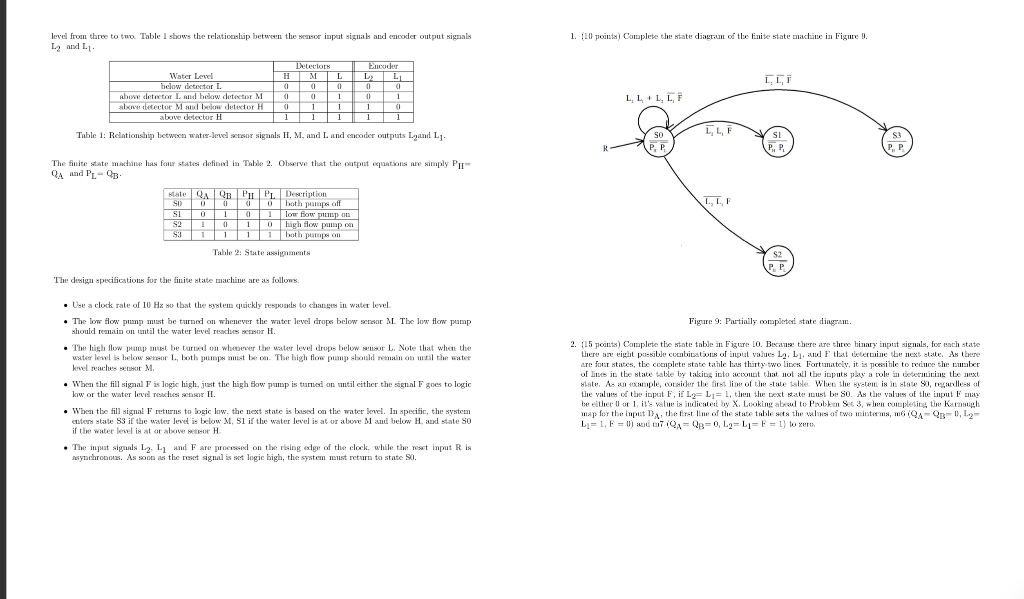
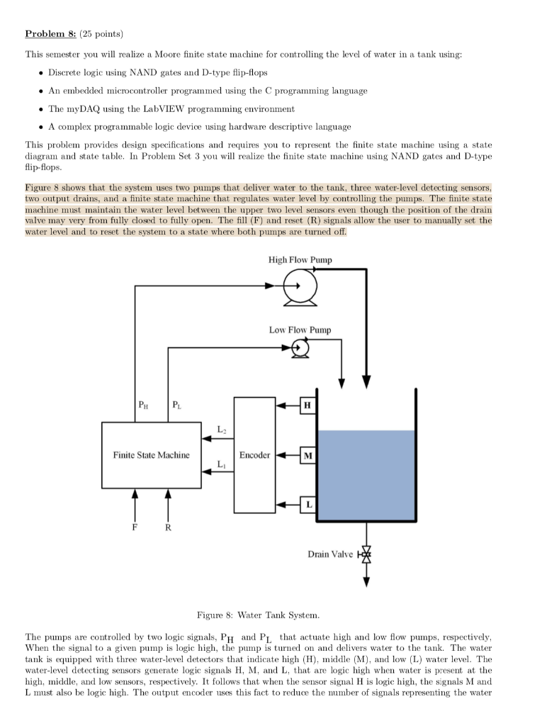
level from three to tuo. Table 1 sbows the relationship between the sense input signals and encoder output signals and L. 1. (10 pont) Complete the state diagram of the finite state machine in Figure 3. L I.LT Water Lear! below detar L. above detector and brow detector M le detector Mand le detector H above detector H Teleco m euder HMLLL 0 0 0 0 0 T O TT 0 1 1 ( 1 1 1 1 1 L.L L , L, F Table 1: Relationship between water-level sensor signals II, M, and Land encoder outputs Land Ly The finite state machine has four states defined in Table 2. Ohserve that the output equations are simply PII- QA and PL-QB state QR PHP Description SO100 0 0 both pamps off SLO1101 low flow pump on S2 0 10 high flow pump on S31111 both pampeon Table 2: State m ents The design specifications for the finite state machine are as follows. Use a clock rate of 10 Hx so that the system quickly reports to changes in water level The low flow pump must be turned on whenever the water level drops below sensor ML The low flow pump should remain on until the water leve reaches besor H. Figure 9: Partially momplete state dingra. The high flow pump must be red on white the water level drops below willor LNote that when the water lewe below Or L. Both pumps met leo. The high flow pump should remain an until the water level reaches or M. . When the fill signal F is logic high, just the high flow pump is turned on until either the signal F goes to logic low or the water levd reaches sensor II. 2. 15 points) Complete the state table in Figure LO. Because there are three binary input signals, for each state there are eight possible combinations of input values La L and Flat cantine the next state. As tbere are four states, the complete state table has thart two lines Fortunately, it is possible to reduce the number of lines in the state table by taking into account that not all tbe inputs per a role in determining tbe next state. Aco ple, Lider the first line of the late tableWhen the s ame is in state So, tales of the value of tbe input F if Lo=L= , then the text estate must be SO. As the value of the input a be therlar 1 it's w i nted by X Loaklumaxsul to Prabkeun S3, when completing the Krug map for the input the first line of the two table is the wo of two interms, IQ -QR-0), L- Li=1, F = 0 DIT IQA=QB=0, L2=L1= F = 1) to zero . When the fill signal F returns to logic low. the next state is based on the water level. In specific, the system uten state S3 if the water level is below M. Sl if the water level is at or above and below H uxl state so il the water kwiator above- The input signals L. L and Fare pro d on the rising age of the clock while the reset input Ris asynchronous. As soon as the rest signal is not logic high, the system must return to state SO. Problem 8: (25 points) This semester you will realize a Moore finite state machine for controlling the level of water in a tank using: Discrete logic using NAND gates and D-type flip-flops An embedded microcontroller programmed using the programming language The myDAQ using the LabVIEW programming environment A complex programmable logic device using hardware descriptive language This problem provides design specifications and requires you to represent the finite state machine using a state diagram and state table. In Problem Set 3 you will realize the finite state machine using NAND gates and D-type flip-flops. Figure 8 shows that the system uses two pumps that deliver water to the tank, three water-level detecting sensors, two output drains, and a finite state machine that regulates water level by controlling the pumps. The finite state machine must maintain the water level between the upper two level sensors even though the position of the drain valve may very from fully closed to fully open. The fill (F) and reset (R) signals allow the user to manually set the water level and to reset the system to a state where both pumps are turned off. High Flow Pump Low Flow Pump PHP Finite State Machine Encoder FR Drain Valve 14 Figure 8: Water Tank System. The pumps are controlled by two logic signals, Ph and PL that actuate high and low flow pumps, respectively, When the signal to a given pump is logic high, the pump is turned on and delivers water to the tank. The water tank is equipped with three water-level detectors that indicate high (H), middle (M), and low (L) water level. The water-level detecting sensors generate logic signals H, M, and L, that are logic high when water is present at the high, middle, and low sensors, respectively. It follows that when the sensor signal H is logic high, the signals M and L must also be logic high. The output encoder uses this fact to reduce the number of signals representing the water level from three to tuo. Table 1 sbows the relationship between the sense input signals and encoder output signals and L. 1. (10 pont) Complete the state diagram of the finite state machine in Figure 3. L I.LT Water Lear! below detar L. above detector and brow detector M le detector Mand le detector H above detector H Teleco m euder HMLLL 0 0 0 0 0 T O TT 0 1 1 ( 1 1 1 1 1 L.L L , L, F Table 1: Relationship between water-level sensor signals II, M, and Land encoder outputs Land Ly The finite state machine has four states defined in Table 2. Ohserve that the output equations are simply PII- QA and PL-QB state QR PHP Description SO100 0 0 both pamps off SLO1101 low flow pump on S2 0 10 high flow pump on S31111 both pampeon Table 2: State m ents The design specifications for the finite state machine are as follows. Use a clock rate of 10 Hx so that the system quickly reports to changes in water level The low flow pump must be turned on whenever the water level drops below sensor ML The low flow pump should remain on until the water leve reaches besor H. Figure 9: Partially momplete state dingra. The high flow pump must be red on white the water level drops below willor LNote that when the water lewe below Or L. Both pumps met leo. The high flow pump should remain an until the water level reaches or M. . When the fill signal F is logic high, just the high flow pump is turned on until either the signal F goes to logic low or the water levd reaches sensor II. 2. 15 points) Complete the state table in Figure LO. Because there are three binary input signals, for each state there are eight possible combinations of input values La L and Flat cantine the next state. As tbere are four states, the complete state table has thart two lines Fortunately, it is possible to reduce the number of lines in the state table by taking into account that not all tbe inputs per a role in determining tbe next state. Aco ple, Lider the first line of the late tableWhen the s ame is in state So, tales of the value of tbe input F if Lo=L= , then the text estate must be SO. As the value of the input a be therlar 1 it's w i nted by X Loaklumaxsul to Prabkeun S3, when completing the Krug map for the input the first line of the two table is the wo of two interms, IQ -QR-0), L- Li=1, F = 0 DIT IQA=QB=0, L2=L1= F = 1) to zero . When the fill signal F returns to logic low. the next state is based on the water level. In specific, the system uten state S3 if the water level is below M. Sl if the water level is at or above and below H uxl state so il the water kwiator above- The input signals L. L and Fare pro d on the rising age of the clock while the reset input Ris asynchronous. As soon as the rest signal is not logic high, the system must return to state SO. Problem 8: (25 points) This semester you will realize a Moore finite state machine for controlling the level of water in a tank using: Discrete logic using NAND gates and D-type flip-flops An embedded microcontroller programmed using the programming language The myDAQ using the LabVIEW programming environment A complex programmable logic device using hardware descriptive language This problem provides design specifications and requires you to represent the finite state machine using a state diagram and state table. In Problem Set 3 you will realize the finite state machine using NAND gates and D-type flip-flops. Figure 8 shows that the system uses two pumps that deliver water to the tank, three water-level detecting sensors, two output drains, and a finite state machine that regulates water level by controlling the pumps. The finite state machine must maintain the water level between the upper two level sensors even though the position of the drain valve may very from fully closed to fully open. The fill (F) and reset (R) signals allow the user to manually set the water level and to reset the system to a state where both pumps are turned off. High Flow Pump Low Flow Pump PHP Finite State Machine Encoder FR Drain Valve 14 Figure 8: Water Tank System. The pumps are controlled by two logic signals, Ph and PL that actuate high and low flow pumps, respectively, When the signal to a given pump is logic high, the pump is turned on and delivers water to the tank. The water tank is equipped with three water-level detectors that indicate high (H), middle (M), and low (L) water level. The water-level detecting sensors generate logic signals H, M, and L, that are logic high when water is present at the high, middle, and low sensors, respectively. It follows that when the sensor signal H is logic high, the signals M and L must also be logic high. The output encoder uses this fact to reduce the number of signals representing the water
Step by Step Solution
There are 3 Steps involved in it

Get step-by-step solutions from verified subject matter experts


