Question
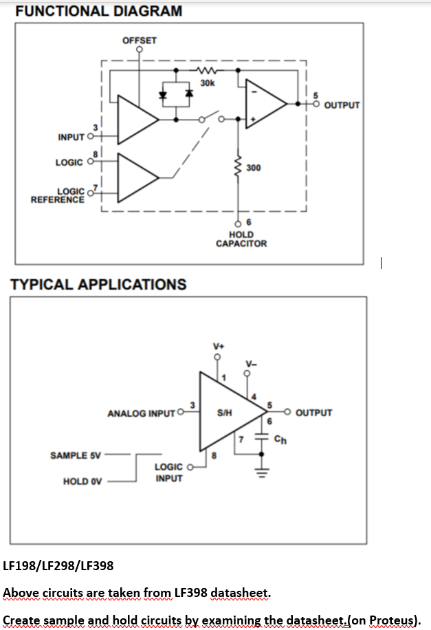
LF398 DATASHEET- http://mdc.custhelp.com/euf/assets/images/KB_856_NatSemi_SampleHold_circuit.pdf create a sample&hold circuit and simulate in Proteus orMultisim.And write a report please. FUNCTIONAL DIAGRAM INPUT LOGIC LOGIC REFERENCE OFFSET www 30k

LF398 DATASHEET- http://mdc.custhelp.com/euf/assets/images/KB_856_NatSemi_SampleHold_circuit.pdf
create a sample&hold circuit and simulate in Proteus orMultisim.And write a report please.
FUNCTIONAL DIAGRAM INPUT LOGIC LOGIC REFERENCE OFFSET www 30k TYPICAL APPLICATIONS www 300 HOLD CAPACITOR OUTPUT ANALOG INPUTO- S/H OUTPUT Ch SAMPLE 5V LOGIC HOLD OV INPUT B LF198/LF298/LF398 Above circuits are taken from LF398 datasheet. wwww Create sample and hold circuits by examining the datasheet.(on Proteus).
Step by Step Solution
3.39 Rating (158 Votes )
There are 3 Steps involved in it
Step: 1
Here are the stepbystep calculations and process to create a sample and hold circuit using the LF398 ...
Get Instant Access to Expert-Tailored Solutions
See step-by-step solutions with expert insights and AI powered tools for academic success
Step: 2

Step: 3

Ace Your Homework with AI
Get the answers you need in no time with our AI-driven, step-by-step assistance
Get StartedRecommended Textbook for
Digital Systems Design Using Verilog
Authors: Charles Roth, Lizy K. John, Byeong Kil Lee
1st edition
1285051076, 978-1285051079
Students also viewed these Law questions
Question
Answered: 1 week ago
Question
Answered: 1 week ago
Question
Answered: 1 week ago
Question
Answered: 1 week ago
Question
Answered: 1 week ago
Question
Answered: 1 week ago
Question
Answered: 1 week ago
Question
Answered: 1 week ago
Question
Answered: 1 week ago
Question
Answered: 1 week ago
Question
Answered: 1 week ago
Question
Answered: 1 week ago
Question
Answered: 1 week ago
Question
Answered: 1 week ago
Question
Answered: 1 week ago
Question
Answered: 1 week ago
Question
Answered: 1 week ago
Question
Answered: 1 week ago
Question
Answered: 1 week ago
Question
Answered: 1 week ago
Question
Answered: 1 week ago
View Answer in SolutionInn App


