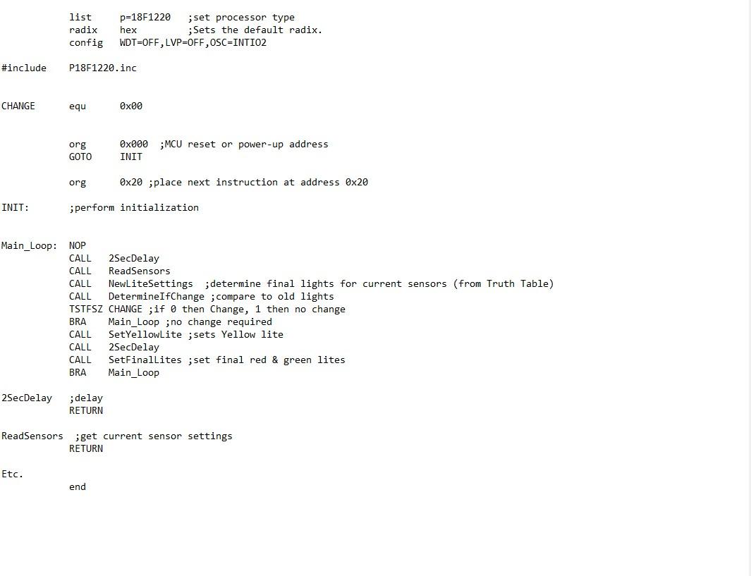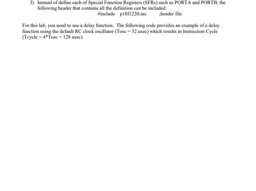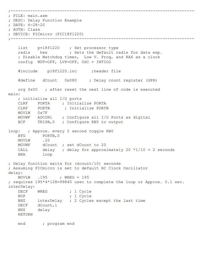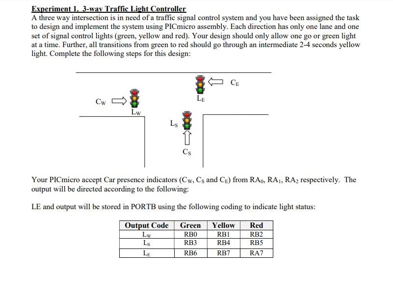


list radix config p=18F1220 ;set processor type hex ;Sets the default radix. WDT=OFF, LVP=OFF, OSC=INTIO2 #include P18F1220.inc CHANGE equ Ox00 org GOTO 0x000;MCU reset or power-up address INIT org 0x20 ;place next instruction at address Ox20 INIT: ; perform initialization Main_Loop: NOP CALL 2SecDelay CALL ReadSensors CALL NewLiteSettings ;determine final lights for current sensors (from Truth Table) CALL DetermineIfChange ; compare to old lights TSTESZ CHANGE ;if O then Change, 1 then no change BRA Main_Loop ; no change required CALL SetYellowlite ;sets Yellow lite 2SecDelay CALL SetFinallites ;set final red & green lites BRA Main_Loop CALL 2SecDelay ; delay RETURN ReadSensors ;get current sensor settings RETURN Etc. end 3) Instead of define each of Special Function Registers (SFRs) such as PORTA and PORTB, the following header that contains all the definition can be included: #include p18f1220.inc ;header file For this lab, you need to use a delay function. The following code provides an example of a delay function using the default RC clock oscillator (Tosc = 32 usec) which results in Instruction Cycle (Tcycle = 4 *Tosc = 128 usec). ; FILE: main.asm ; DESC: Delay Function Example ; DATE: 6-28-20 ; AUTH: Class ; DEVICE: PICmicro (PIC18F1220) list p=18f1220 ; Set processor type radix hex ; Sets the default radix for data exp. ; Disable Watchdog timer, Low V. Prog, and RA6 as a clock config WDT=OFF, LVP=OFF, OSC = INTI02 #include p18f1220.inc ; header file #define dCount 0x080 Delay count register (GPR) org Ox00 ; after reset the next line of code is executed main: ; initialize all I/O ports CLRE PORTA ; Initialize PORTA CLRF PORTB ; Initialize PORTB MOVLW Ox75 MOVWE ADCONI ; Configure all I/O Ports as digital BCF TRISB, 0 ; Configure RBO to output .20 loop: ; Approx. every 2 second toggle RBO BTG PORTB, 0 MOVLW MOVWE dCount ; set dcount to 20 CALL delay ; delay for approximately 20*1/10 = 2 seconds BRA loop ; Delay function waits for (dcount/10) seconds ; Assuming PICmicro is set to default RC clock Oscillator delay: MOVLW 195 ; WREG - 195 ; requires 195* 4* 128=99840 usec to complete the loop or Approx. 0.1 sec. interDelay: DECF WREG ; 1 Cycle NOP ; 1 Cycle BNZ inter Delay ; 2 Cycles except the last time DECF dCount, 1 BNZ delay RETURN end ; program end Experiment 1. 3-way Traffic Light Controller A three way intersection is in need of a traffic signal control system and you have been assigned the task to design and implement the system using PICmicro assembly. Each direction has only one lane and one set of signal control lights (green, yellow and red). Your design should only allow one go or green light at a time. Further, all transitions from green to red should go through an intermediate 2-4 seconds yellow light. Complete the following steps for this design: CE LE Cw ) Lw LS Cs Your PICmicro accept Car presence indicators (Cw, Cs and Ce) from RA, RA, RA, respectively. The output will be directed according to the following: LE and output will be stored in PORTB using the following coding to indicate light status: Output Code Green Yellow Red Lw RBO RBI RB2 Ls RB3 RB4 RBS LE RB6 RB7 RAZ list radix config p=18F1220 ;set processor type hex ;Sets the default radix. WDT=OFF, LVP=OFF, OSC=INTIO2 #include P18F1220.inc CHANGE equ Ox00 org GOTO 0x000;MCU reset or power-up address INIT org 0x20 ;place next instruction at address Ox20 INIT: ; perform initialization Main_Loop: NOP CALL 2SecDelay CALL ReadSensors CALL NewLiteSettings ;determine final lights for current sensors (from Truth Table) CALL DetermineIfChange ; compare to old lights TSTESZ CHANGE ;if O then Change, 1 then no change BRA Main_Loop ; no change required CALL SetYellowlite ;sets Yellow lite 2SecDelay CALL SetFinallites ;set final red & green lites BRA Main_Loop CALL 2SecDelay ; delay RETURN ReadSensors ;get current sensor settings RETURN Etc. end 3) Instead of define each of Special Function Registers (SFRs) such as PORTA and PORTB, the following header that contains all the definition can be included: #include p18f1220.inc ;header file For this lab, you need to use a delay function. The following code provides an example of a delay function using the default RC clock oscillator (Tosc = 32 usec) which results in Instruction Cycle (Tcycle = 4 *Tosc = 128 usec). ; FILE: main.asm ; DESC: Delay Function Example ; DATE: 6-28-20 ; AUTH: Class ; DEVICE: PICmicro (PIC18F1220) list p=18f1220 ; Set processor type radix hex ; Sets the default radix for data exp. ; Disable Watchdog timer, Low V. Prog, and RA6 as a clock config WDT=OFF, LVP=OFF, OSC = INTI02 #include p18f1220.inc ; header file #define dCount 0x080 Delay count register (GPR) org Ox00 ; after reset the next line of code is executed main: ; initialize all I/O ports CLRE PORTA ; Initialize PORTA CLRF PORTB ; Initialize PORTB MOVLW Ox75 MOVWE ADCONI ; Configure all I/O Ports as digital BCF TRISB, 0 ; Configure RBO to output .20 loop: ; Approx. every 2 second toggle RBO BTG PORTB, 0 MOVLW MOVWE dCount ; set dcount to 20 CALL delay ; delay for approximately 20*1/10 = 2 seconds BRA loop ; Delay function waits for (dcount/10) seconds ; Assuming PICmicro is set to default RC clock Oscillator delay: MOVLW 195 ; WREG - 195 ; requires 195* 4* 128=99840 usec to complete the loop or Approx. 0.1 sec. interDelay: DECF WREG ; 1 Cycle NOP ; 1 Cycle BNZ inter Delay ; 2 Cycles except the last time DECF dCount, 1 BNZ delay RETURN end ; program end Experiment 1. 3-way Traffic Light Controller A three way intersection is in need of a traffic signal control system and you have been assigned the task to design and implement the system using PICmicro assembly. Each direction has only one lane and one set of signal control lights (green, yellow and red). Your design should only allow one go or green light at a time. Further, all transitions from green to red should go through an intermediate 2-4 seconds yellow light. Complete the following steps for this design: CE LE Cw ) Lw LS Cs Your PICmicro accept Car presence indicators (Cw, Cs and Ce) from RA, RA, RA, respectively. The output will be directed according to the following: LE and output will be stored in PORTB using the following coding to indicate light status: Output Code Green Yellow Red Lw RBO RBI RB2 Ls RB3 RB4 RBS LE RB6 RB7 RAZ


