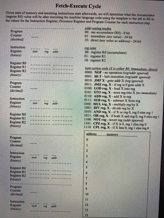
Look at the following FetchExecute-template please please!
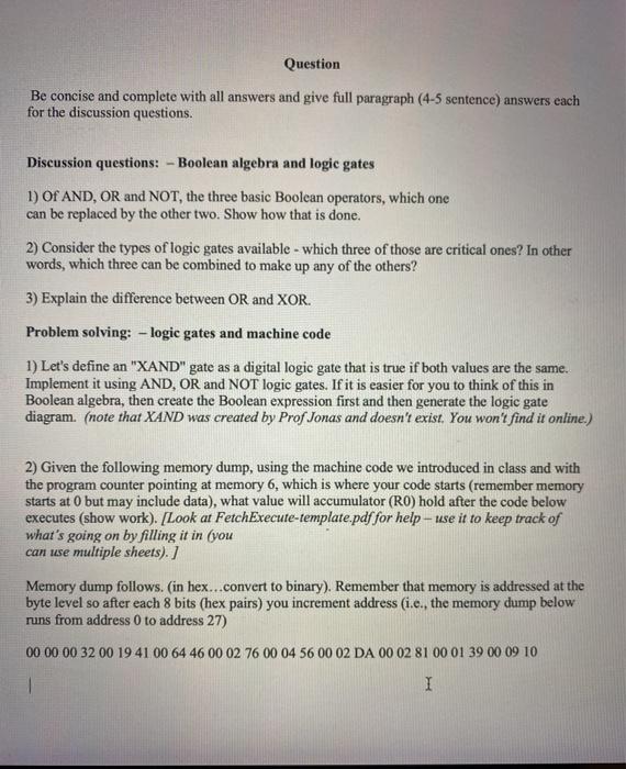
Question Be concise and complete with all answers and give full paragraph (4-5 sentence) answers each for the discussion questions. Discussion questions: - Boolean algebra and logic gates 1) Of AND, OR and NOT the three basic Boolean operators, which one can be replaced by the other two. Show how that is done. 2) Consider the types of logic gates available - which three of those are critical ones? In other words, which three can be combined to make up any of the others? 3) Explain the difference between OR and XOR. Problem solving: - logic gates and machine code 1) Let's define an "XAND" gate as a digital logic gate that is true if both values are the same. Implement it using AND, OR and NOT logic gates. If it is easier for you to think of this in Boolean algebra, then create the Boolean expression first and then generate the logic gate diagram. (note that XAND was created by Prof Jonas and doesn't exist. You won't find it online.) 2) Given the following memory dump, using the machine code we introduced in class and with the program counter pointing at memory 6, which is where your code starts (remember memory starts at O but may include data), what value will accumulator (RO) hold after the code below executes (show work). [Look at FetchExecute-template.pdf for help - use it to keep track of what's going on by filling it in (you can use multiple sheets). ] Memory dump follows. (in hex...convert to binary). Remember that memory is addressed at the byte level so after each 8 bits (hex pairs) you increment address (i.e., the memory dump below runs from address 0 to address 27) 00 00 00 32 00 19 41 00 64 46 00 02 76 00 04 56 00 02 DA 00 02 81 00 01 39 00 09 10 I Fetch-Execute Cycle Given state of memory and assuming instructions start afterwards, we will determine what the Accumulator (register RO) value will be after executing the machine language code using the template to the left to fill in the values for the Instruction Register, Processor Register and Program Counter for each instruction step. addressing modes Program 00: use accumulator (RO)- 8 bit Counter 01: immediate (use value) - 24 bit (decimal) 10: direct une value as address) - 24 bit Instruction Register (binary) regaddr register 00: register RO (accumulator) 01: register RI 10: register R2 Register RO Register RI Register R2 (binary) Program Counter (decimal) Instruction Register (binary) instr-uction code X is either Rimmediate direct) 0000: NOP - no operation (reg/addr ignored) 0001: HLT - halt execution (reg/addr ignored) 0010: JMP X - goto addr X (reg ignored) 0011: JMZ reg, X - if reg is 0 goto addr X 0100: LOD reg, X - load X into reg 0101: STO reg, X - store reg into X (no immediate) 0110: ADD reg, X-add X to reg 0111: SUB reg, X - subtract X from reg 1000: MUL reg, X.multiply reg by X 1001: DIV reg, X - divide reg by X 1010: AND reg, X - if X or reg 0, reg o else reg 1 1011: OR reg, X - if both X and reg 0,reg else reg! 1100: NOT reg - invert reg (addr ignored) 1101: CPZ reg. X - if X is 0, reg 1 else reg 0 1110: CPL reg, X - if X less 0, reg 1 else reg 0 address memory TEST reg addr Register RO Register R1 Register R2 ( (binary) 0 Program Counter (decimal) 1 2 3 Instruction Register (binary) Instr reg addr 4 Register RO Register R1 Register R2 (binary) 6 8 9 Program Counter (decimal) 10 11 Instruction Register (binary) 12 FEE addr 13 IS


