Answered step by step
Verified Expert Solution
Question
1 Approved Answer
Many people has gave answer for this and all them are wrong Also WE REQUIRED CIRCUIT DIAGRAM GIVEN BELOW Specifications: Part-3 Part-3: Description In this
Many people has gave answer for this and all them are wrong Also WE REQUIRED CIRCUIT DIAGRAM GIVEN BELOW
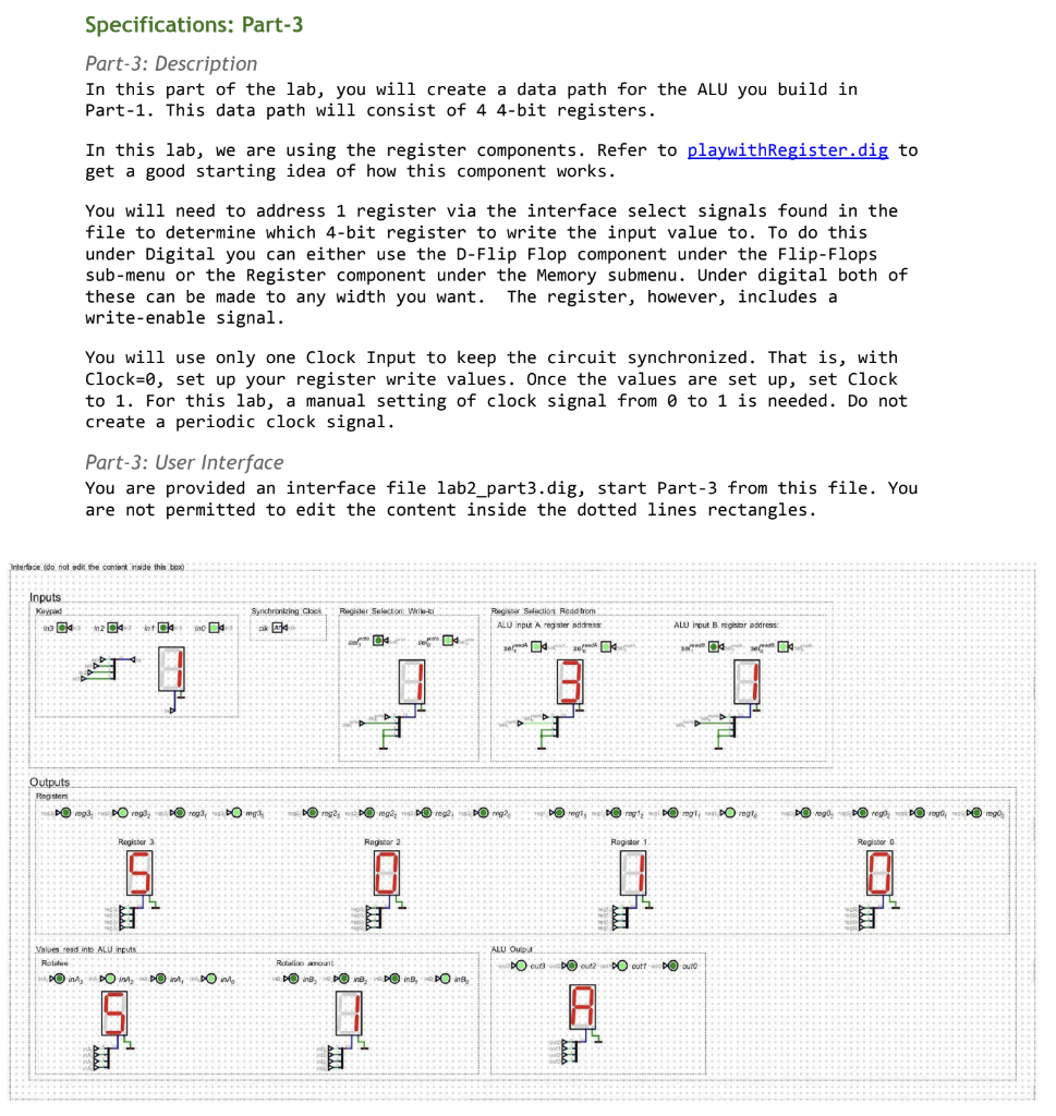
Specifications: Part-3 Part-3: Description In this part of the lab, you will create a data path for the ALU you build in Part-1. This data path will consist of 4 4-bit registers. In this lab, we are using the register components. Refer to playwithRegister. dig to get a good starting idea of how this component works. You will need to address 1 register via the interface select signals found in the file to determine which 4-bit register to write the input value to. To do this under Digital you can either use the D-Flip Flop component under the Flip-Flops sub-menu or the Register component under the Memory submenu. Under digital both of these can be made to any width you want. The register, however, includes a write-enable signal. You will use only one Clock Input to keep the circuit synchronized. That is, with Clock=0, set up your register write values. Once the values are set up, set Clock to 1. For this lab, a manual setting of clock signal from to 1 is needed. Do not create a periodic clock signal. Part-3: User Interface You are provided an interface file lab2_part3.dig, start Part-3 from this file. You are not permitted to edit the content inside the dotted lines rectangles. Intarface (do toot odi the contert inside this tox) Qutputs Pogisters. rog3rog4bO2bOinogbO rog21=DO2rog2BOreg2;DOreg2 I Values tead inte. ALU ircuts. Part-3: Example In this design, the user can choose out of the 4 registers where to store the 4-bit value which needs to be rotated (inA from part-1) and also which register to store the rotation amount (inB from part-1), using the selwrite register selection inputs. The user ensures they direct these two registers to the correct Register Selection: Read From values for inA and inB inputs values to the ALU. In the figure above, we have written the value 5 to Register 3 and the value 1 to Register 1. Then, we read from Register 3 the value 5 to ALU input A and read from Register 1 the value 1 to ALU input B. Rotating 5 right by 1 b it results in {1,0, 1,0} displayed in the ALU Output as hexadecimal A
Step by Step Solution
There are 3 Steps involved in it
Step: 1
Get Instant Access to Expert-Tailored Solutions
See step-by-step solutions with expert insights and AI powered tools for academic success
Step: 2
Step: 3
Ace Your Homework with AI
Get the answers you need in no time with our AI-driven, step-by-step assistance
Get Started