Question: MATLAB CODE I need help understanding what (x) is in the question. I don't know how to relate x to the number of nodes N
MATLAB CODE
I need help understanding what (x) is in the question. I don't know how to relate x to the number of nodes N


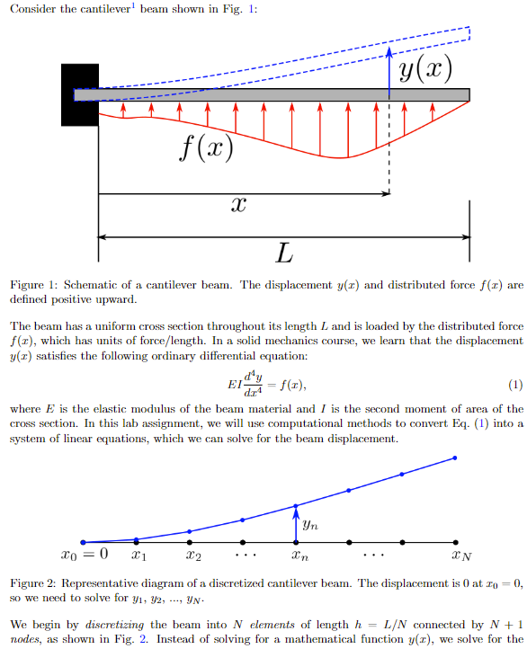
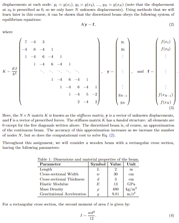
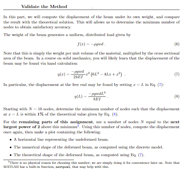
Consider the cantilever 1 beam shown in Fig. 1: Figure 1: Schematic of a cantilever beam. The displacement y(x) and distributed force f(x) are defined positive upward. The beam has a uniform cross section throughout its length L and is loaded by the distributed force f(x), which has units of force/length. In a solid mechanics course, we learn that the displacement y(x) satisfies the following ordinary differential equation: EIdx4d4y=f(x), where E is the elastic modulus of the beam material and I is the second moment of area of the cross section. In this lab assignment, we will use computational methods to convert Eq. (1) into a system of linear equations, which we can solve for the beam displacement. Figure 2: Representative diagram of a discretized cantilever beam. The displacement is 0 at x0=0, so we need to solve for y1,y2,,yN. We begin by discretizing the beam into N elements of length h=L/N connected by N+1 nodes, as shown in Fig. 2. Instead of solving for a mathematical function y(x), we solve for the displacements at each node: y1y(x1),y2y(x2),,yNy(xN) (note that the displacement at x0 is prescribed as 0 , so we only have N unknown displacements). Using methods that we will learn later in this course, it can be shown that the discretized beam obeys the following system of equilibrium equations: Ky=f where Here, the NN matrix K is known as the stiffness matrix, y is a vector of unknown displacements, and f is a vector of prescribed forces. The stiffness matrix K has a banded structure: all elements are 0 except for the five diagonals written above. The discretized beam is, of course, an approximation of the continuous beam. The accuracy of this approximation increases as we increase the number of nodes N, but so does the computational cost to solve Eq. (2). Throughout this assignment, we will consider a wooden beam with a rectangular cross section, having the following parameters: For a rectangular cross section, the second moment of area I is given by: I=12wd3 In this part, we will compute the displacement of the beam under its own weight, and compare the result with the theoretical solution. This will allows us to determine the minimum number of nodes to obtain satisfactory accuracy. The weight of the beam generates a uniform, distributed load given by f(x)=gwd Note that this is simply the weight per unit volume of the material, multiplied by the cross sectional area of the beam. In a course on solid mechanics, you will likely learn that the displacement of the beam may be found via hand calculation: y(x)=24EIgwdx2(6L24Lx+x2) In particular, the displacement at the free end may be found by setting x=L in Eq. (7): y(L)=8EIgwdL4. Starting with N=10 nodes, determine the minimum number of nodes such that the displacement at x=L is within 1% of the theoretical value given by Eq. (8). For the remaining parts of this assignment, use a number of nodes N equal to the next largest power of 2 above this minimum 2. Using this number of nodes, compute the displacement once again, then make a plot containing the following: - A horizontal line representing the undeformed beam. - The numerical shape of the deformed beam, as computed using the discrete model. - The theoretical shape of the deformed beam, as computed using Eq. (7). 2 There is no physical reason for choosing this number; we are simply doing it for convenience later on. Note that MATLAB has a built-in function, nextpou 2 , that may help with this. Consider the cantilever 1 beam shown in Fig. 1: Figure 1: Schematic of a cantilever beam. The displacement y(x) and distributed force f(x) are defined positive upward. The beam has a uniform cross section throughout its length L and is loaded by the distributed force f(x), which has units of force/length. In a solid mechanics course, we learn that the displacement y(x) satisfies the following ordinary differential equation: EIdx4d4y=f(x), where E is the elastic modulus of the beam material and I is the second moment of area of the cross section. In this lab assignment, we will use computational methods to convert Eq. (1) into a system of linear equations, which we can solve for the beam displacement. Figure 2: Representative diagram of a discretized cantilever beam. The displacement is 0 at x0=0, so we need to solve for y1,y2,,yN. We begin by discretizing the beam into N elements of length h=L/N connected by N+1 nodes, as shown in Fig. 2. Instead of solving for a mathematical function y(x), we solve for the displacements at each node: y1y(x1),y2y(x2),,yNy(xN) (note that the displacement at x0 is prescribed as 0 , so we only have N unknown displacements). Using methods that we will learn later in this course, it can be shown that the discretized beam obeys the following system of equilibrium equations: Ky=f where Here, the NN matrix K is known as the stiffness matrix, y is a vector of unknown displacements, and f is a vector of prescribed forces. The stiffness matrix K has a banded structure: all elements are 0 except for the five diagonals written above. The discretized beam is, of course, an approximation of the continuous beam. The accuracy of this approximation increases as we increase the number of nodes N, but so does the computational cost to solve Eq. (2). Throughout this assignment, we will consider a wooden beam with a rectangular cross section, having the following parameters: For a rectangular cross section, the second moment of area I is given by: I=12wd3 In this part, we will compute the displacement of the beam under its own weight, and compare the result with the theoretical solution. This will allows us to determine the minimum number of nodes to obtain satisfactory accuracy. The weight of the beam generates a uniform, distributed load given by f(x)=gwd Note that this is simply the weight per unit volume of the material, multiplied by the cross sectional area of the beam. In a course on solid mechanics, you will likely learn that the displacement of the beam may be found via hand calculation: y(x)=24EIgwdx2(6L24Lx+x2) In particular, the displacement at the free end may be found by setting x=L in Eq. (7): y(L)=8EIgwdL4. Starting with N=10 nodes, determine the minimum number of nodes such that the displacement at x=L is within 1% of the theoretical value given by Eq. (8). For the remaining parts of this assignment, use a number of nodes N equal to the next largest power of 2 above this minimum 2. Using this number of nodes, compute the displacement once again, then make a plot containing the following: - A horizontal line representing the undeformed beam. - The numerical shape of the deformed beam, as computed using the discrete model. - The theoretical shape of the deformed beam, as computed using Eq. (7). 2 There is no physical reason for choosing this number; we are simply doing it for convenience later on. Note that MATLAB has a built-in function, nextpou 2 , that may help with this
Step by Step Solution
There are 3 Steps involved in it

Get step-by-step solutions from verified subject matter experts


