Question
Modify the C code below for the STM32F411RE microcontroller such that if follows the following specifications: C code: #include #include void GPIO_Init(void); void OC_Init(void); int
Modify the C code below for the STM32F411RE microcontroller such that if follows the following specifications:


C code:
#include
void GPIO_Init(void); void OC_Init(void);
int main(void) { GPIO_Init(); OC_Init();
int i; while (1) { for (i = 0; i CCR1 = 896; // set capture/compare register 1 for (i = 0; i CCR1 = 256; // set capture/compare register 1 } }
void GPIO_Init(void) { RCC->AHB1ENR |= (1
GPIOA->MODER |= (1MODER &= ~(1
GPIOA->AFR[0] &= ~(1AFR[0] &= ~(1AFR[0] &= ~(1AFR[0] |= (1
GPIOA->OTYPER &= ~(1
GPIOA->PUPDR &= ~(1PUPDR &= ~(1
GPIOA->OSPEEDR |= (1OSPEEDR &= ~(1
void OC_Init(void) { RCC->APB1ENR |= (1
TIM2->CR1 &= ~(1CR1 &= ~(1
TIM2->CR1 &= ~(1
TIM2->PSC = 99; // set clock prescaler
TIM2->ARR = 1279; // set auto-reload value
TIM2->CCR1 = 256; // set capture/compare register 1
TIM2->CCMR1 &= ~(1CCMR1 &= ~(1
TIM2->CCMR1 |= (1CCMR1 |= (1CCMR1 |= (1
TIM2->CCMR1 |= (1
TIM2->CCER &= ~(1
TIM2->CCER |= (1
TIM2->BDTR |= (1
TIM2->EGR |= (1
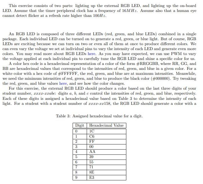
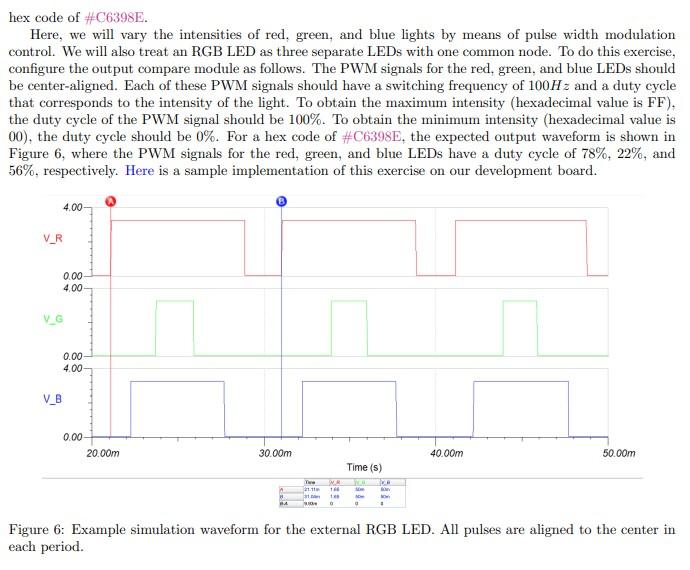
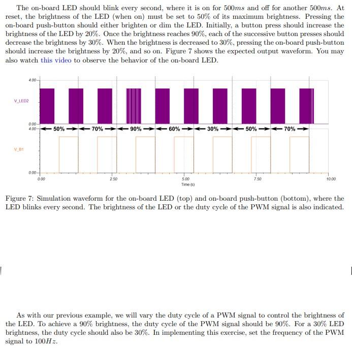
TIM2->CR1 |= (1 This exercise consists of two parts: lighting up the external RGB LED, and lighting up the on-board LED. Assume that the timer peripheral clock has a frequency of 16MHz. Assume also that a human eye cannot detect flicker at a refresh rate higher than 100Hz. An RGB LED is composed of three different LEDs (red, green, and blue LEDs) combined in a single package. Each individual LED can be turned on to generate a red, green, or blue light. But of course, RGB LEDs are exciting because we can turn on two or even all of them at once to produce different colors. We can even vary the voltage we set at individual pins to vary the intensity of each LED and generate even more colors. You may read more about RGB LEDs here. As you may have expected, we can use PWM to vary the voltage applied at each individual pin to carefully tune the RGB LED and shine a specific color for us. A color hex code is a hexadecimal representation of a color of the form \#RRGGBB, where RR, GG, and BB are hexadecimal values that correspond to the intensities of red, green, and blue in a given color. For a white color with a hex code of \#FFFFFF, the red, green, and blue are at maximum intensities. Meanwhile, we need the minimum intensities of red, green, and blue to produce the black color (\#000000). Try tweaking the red, green, and blue values here, and see how the color changes. For this exercise, the external RGB LED should produce a color based on the last three digits of your student number, xxxx-xxabc: digits a,b, and c control the intensities of red, green, and blue, respectively. Each of these digits is assigned a hexadecimal value based on Table 3 to determine the intensity of each light. For a student with a student number of xxxxxx158, the RGB LED should generate a color with a Table 3: Assigned hexadecimal value for a digit. hex code of \#C6398E. Here, we will vary the intensities of red, green, and blue lights by means of pulse width modulation control. We will also treat an RGB LED as three separate LEDs with one common node. To do this exercise, configure the output compare module as follows. The PWM signals for the red, green, and blue LEDs should be center-aligned. Each of these PWM signals should have a switching frequency of 100Hz and a duty cycle that corresponds to the intensity of the light. To obtain the maximum intensity (hexadecimal value is FF), the duty cycle of the PWM signal should be 100%. To obtain the minimum intensity (hexadecimal value is 00 ), the duty cycle should be 0%. For a hex code of \#C6398E, the expected output waveform is shown in Figure 6, where the PWM signals for the red, green, and blue LEDs have a duty cycle of 78%,22%, and 56%, respectively. Here is a sample implementation of this exercise on our development board. Figure 6: Example simulation waveform for the external RGB LED. All pulses are aligned to the center in each period. The on-board LED should blink every second, where it is on for 500ms and off for another 500ms. At reset, the brightness of the LED (when on) must be set to 50% of its maximum brightness. Pressing the on-board push-button should either brighten or dim the LED. Initially, a button press should increase the brightness of the LED by 20%. Once the brightness reaches 90%, each of the successive button presses should decrease the brightness by 30%. When the brightness is decreased to 30%, pressing the on-board push-button should increase the brightness by 20%, and so on. Figure 7 shows the expected output waveform. You may also watch this video to observe the behavior of the on-board LED. Figure 7: Simulation waveform for the on-board LED (top) and on-board push-button (bottom), where the LED blinks every second. The brightness of the LED or the duty cycle of the PWM signal is also indicated. As with our previous example, we will vary the duty cycle of a PWM signal to control the brightness of the LED. To achieve a 90% brightness, the duty cycle of the PWM signal should be 90%. For a 30% LED brightness, the duty cycle should also be 30%. In implementing this exercise, set the frequency of the PWM signal to 100Hz
Step by Step Solution
There are 3 Steps involved in it
Step: 1

Get Instant Access to Expert-Tailored Solutions
See step-by-step solutions with expert insights and AI powered tools for academic success
Step: 2

Step: 3

Ace Your Homework with AI
Get the answers you need in no time with our AI-driven, step-by-step assistance
Get Started


