

modify your ReadKeyPad() function to support edge detection; When user presses and holds a key, return the ASCII code to the main code. But if
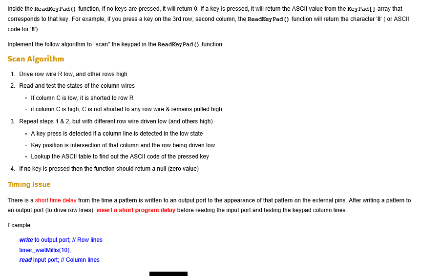
modify your ReadKeyPad() function to support edge detection; When user presses and holds a key, return the ASCII code to the main code. But if the key is held, the function will not return the ASCII code. Unless user release key or presses another key.
please help me to finish this Ti tiva series code, it`s TM4C123G thanks
#include
char str[100]; char ReadKeyPad(); char ch; int main(void) { PEZOBJ_LCD lcd; uint16_t i = 0; // GPIO Initialization and Configuration // 1. Enable Clock on GPIOs SYSCTL->RCGCGPIO |= 0x00; // allow time for clock to stabilize while ((SYSCTL->PRGPIO & 0x1B) != 0x1B) {}; // 2. Unlock PD7 and/or PF0 for TM4C 123G // 3. Config AMSEL to disable analog function GPIOA ->AMSEL=0x00; GPIOB ->AMSEL = 0x00; GPIOD -> AMSEL = 0x00; GPIOE -> AMSEL =0x00; // 4. Config PCTL to select 0-GPIO GPIOA->PCTL=0x00; GPIOB->PCTL=0x00; GPIOD->PCTL=0x00; GPIOE->PCTL=0x00; // 5. Set AFSEL bits to 0 GPIOA -> AFSEL =0x00; GPIOB -> AFSEL =0x00;GPIOD -> AFSEL =0x00;GPIOE -> AFSEL =0x00; // 6. Set DIR to 0 for input, 1 for output GPIOE ->DIR =0x0F; GPIOD-> DIR=0x3E; GPIOB->DIR=0x03; GPIOA->DIR= 0x00; // 7. Set PUR/PDR/ODR bits to 1 to enable internal pull-up/-down resistir and/or open-drain GPIOB->PUR=0x03; GPIOE->PUR=0x30; GPIOB->PUR=0X10; GPIOA->PUR=0xE0; // 8. Set DEN bits to 1 to enable all pins GPIOA->DEN=0xE0; GPIOD->DEN=0x0F; GPIOE->DEN= 0x3E; GPIOB->DEN=0x13; lcd = ezLCD_Create(); ezLCD_Connect_DataPort(lcd, GPIOD, PIN_3_0); ezLCD_Connect_ENPin(lcd, GPIOE, PIN1); ezLCD_Connect_RSPin(lcd, GPIOE, PIN2); ezLCD_Connect_RWPin(lcd, GPIOE, PIN3); ezLCD_Start(lcd); ezLCD_ClearDisplay(lcd); ezLCD_Position(lcd, 1, 0); ezLCD_PrintString(lcd, "HELLO");
while(1){ char ch = ReadKeyPad(); if (ch == '*'){ i *= 100; ezLCD_ClearDisplay(lcd); } if (ch == '#') i = 0; if (ch >='0' && ch
char ReadKeyPad() { int row, col;
char key =0; for (row =0; row 0, R2 ,R3, R4=>1 break; case 2: break;
case 3: break ; } timer_waitMillis(10); col = (( GPIOB ->DATA & 0x10) >> 4) ; if (!(col& 0x01)) key =KeyPad [row] [1] ; // check c1 //check c2 // check c3 // check C4 if (key) break; } }
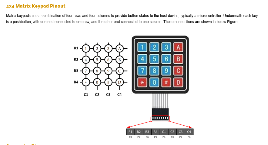
x4 Matrix Keypad Pinout Matrix keypads use a combination of four rows and four columns to provide button states to the host device, typically a microcontroller. Underneath each key is a pushbutton, with one end connected to one row, and the other end connected to one column. These connections are shown in below Figure R2 456 B 4 C1 C2 C3 C4 R1 R2 R3 R4 C1 C2 C3 C4 P7 P6 PS P4 P3P2P1 x4 Matrix Keypad Pinout Matrix keypads use a combination of four rows and four columns to provide button states to the host device, typically a microcontroller. Underneath each key is a pushbutton, with one end connected to one row, and the other end connected to one column. These connections are shown in below Figure R2 456 B 4 C1 C2 C3 C4 R1 R2 R3 R4 C1 C2 C3 C4 P7 P6 PS P4 P3P2P1Step by Step Solution
There are 3 Steps involved in it
Step: 1

See step-by-step solutions with expert insights and AI powered tools for academic success
Step: 2

Step: 3
Ace Your Homework with AI
Get the answers you need in no time with our AI-driven, step-by-step assistance
Get Started
Authors: Francesca Cesarini ,Silvio Salza
1st Edition
3540179429, 978-3540179429