Answered step by step
Verified Expert Solution
Question
1 Approved Answer
Modular Crop Growth Model and Simulation Suggested Language G+ Maximum Team Size 4 Skill Set C++ GUI time step within this loop. The weather object
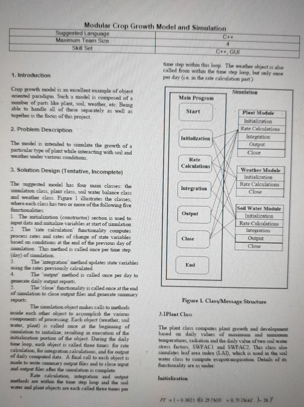
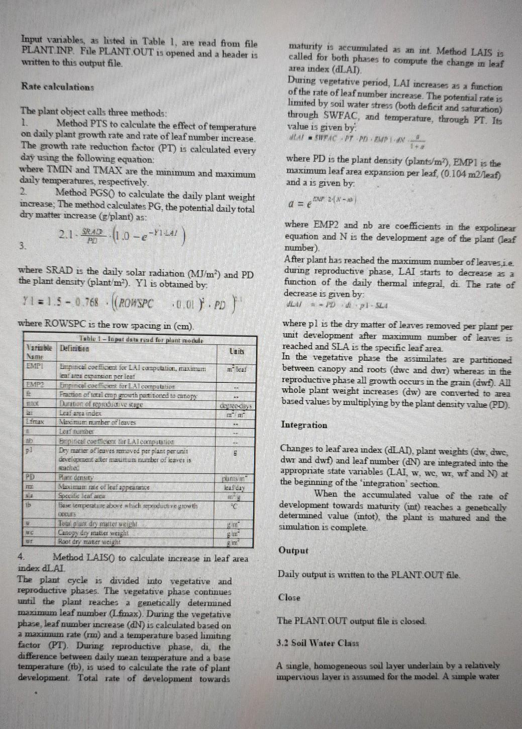
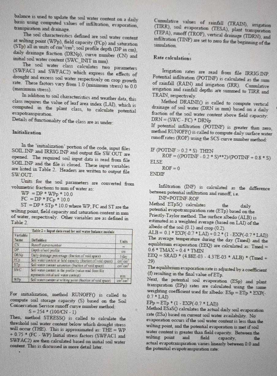
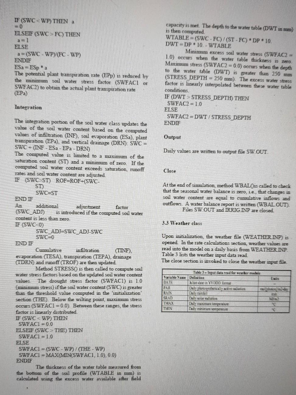
Modular Crop Growth Model and Simulation Suggested Language G+ Maximum Team Size 4 Skill Set C++ GUI time step within this loop. The weather object is also called from within the time step loop, but only once per day (ie in the rate calculation part.) 1. Introduction Simulation Main Program Crop growth model is an excellent example of object oriented paradigm. Such a model is composed of a number of parts like plant, soil, weather, etc. Being able to handle all of these separately as well as together is the focus of this project. Start 2. Problem Description Plant Module Initialization Rate Calculations Integration Output Close Initialization The model is intended to simulate the growth of a particular type of plant while interacting with soil and weather under vanous conditions. Rate Calculations 3. Solution Design (Tentative, Incomplete) Weather Module Initialization Rate Caleulations Close Integration Output Soil Water Module Initialization Rate Calculations Integration Output Cluse Close End The suggested model has four main classes: the simulation class, plant class, soil water balance class and weather class. Figure 1 illustrates the classes, where each elass has two or more of the following five functionalities: 1. The initialization (constructor) section is used to input data and initialize variables at start of simulation The rate calculation functionality computes process rates and rates of change of state variables based on conditions at the end of the previous day of simulation. This method is called once per time step (day) of simulation The 'integration method updates state variables using the rates previously calculated. The output method is called once per day to generate daily output reports. The 'close functionality is called once at the end of simulation to close output files and generate summary reports The simulation object makes calls to methods inside each other object to accomplish the various components of processing. Each object (weather, soil water, plant) is called once at the beginning of simulation to initialize, resulting in execution of the initialization portion of the object. During the daily time loop, each object is called three times: for rate calculation, for integration calculations, and for output of daily computed data. A final call to each object is made to write summary output files and to close input and output files after the simulation is complete Rate calculation, integration and output methods are within the time step loop and the soil water and plant objects are each called three times per Figure 1. Class Message Structure 3.1 Plant Class The plant class computes plant growth and development based on daily values of maximum and munimum temperatuues, radiation and the daily value of two soll water stress factors, SWFACI and SWFACR. This class also simulates leaf area index (LAD, which is used in the soil water class to compute evapouauupuanon. Details of its functionality are as under Initialization FT = 1-2002 O ES TAN - 0.5 - 26 Input variables, as listed in Table 1, are read from file PLANT INP. File PLANT OUT is opened and a header is written to this output file. Rate calculations The plant object calls three methods: 1. Method PTS to calculate the effect of temperature on daily plant growth rate and rate of leaf number increase. The growth rate reduction factor (PT) is calculated every day using the following equation: where TMN and TMAX are the minimum and maximum daily temperatures, respectively. 2. Method PGS() to calculate the daily plant weight increase: The method calculates PG, the potential daily total dry matter increase (g plant) as: maturity is aecummilated as an int. Method LAIS is called for both phases to compute the change in leaf area index (LAT). During vegetative period, LAI increases as a function of the rate of leaf number increase. The potential rate is limited by soil water stress (both deficit and saturation) through SWFAC, and temperature, through PT. Its value is given by MAI - SWACHST MOEmpian, where PD is the plant density (plants/m%), EMPI is the maximum leaf area expansion per leaf, (0.104 m2/leaf) and a is given by EM 20 2.1 Stan (1.0-c-1104) 3. where EMP2 and nb are coefficients in the expolinear equation and N is the development age of the plant (leaf number) After plant has reached the maximum number of leavesie during reproductive phase, LAI starts to decrease as a function of the daily thermal integral, di. The rate of decrease is given by where SRAD is the daily solar radiation (MJ/m) and PD the plant density (plant/m?). Yl is obtained by Y1 = 1,5 - 0.768 - (ROWSPC where ROWSPC is the row spacing in (em). Table 1 - la data read for plant module Tarbie Delinten me Einninc. coeffice Lal terpular, maximum catares espansionat Forpincat ceciet turi alcomputan Fraction af total.cooperth partied to stop where pl is the dry matter of leaves removed per plant per unit development after maximum number of leaves is reached and SLA is the specifie leaf area. In the vegetative phase the assimilates are partitioned between canopy and roots (dwe and dwr) whereas in the reproductive phase all growth occurs in the grain (dwf). All whole plant weight increases (dw) are converted to area based values by multiplying by the plant density value (PD). ned Lealance index Nam mather of cus ber Integration Domater pficaves med mer plant porumet celent aller mume mureher of beures is 5 Hans enery TE Waxima recalculannende Changes to leaf area index (ALAT), plant weights (ew, dwe, dwr and dwf) and leaf number (N) are integrated into the appropnate state variables (LAI, w, we, wr, wf and N at the beginning of the 'integration section. When the accumulated value of the rate of development towards maturity (int) reaches a genetically determined value intot), the plant is matured and the simulation is complete. ib like about which repude oth DES 40 Canon de match ST Output Daily output is written to the PLANT.OUT file. Close 4. Method LAISO to calculate increase in leaf area index LAI The plant cycle is divided into vegetative and reproductive phases. The vegetative phase continues until the plant reaches a genetically determined maximum leaf number (Ifmax). During the vegetative phase, leaf number increase (DN) is calculated based on a maximum rate (mm) and a temperature based limiting factor (PT). During reproductive phase, dithe difference between daily mean temperature and a base temperature (tb), is used to calculate the rate of plant development. Total rate of development towards The PLANT OUT output file is closed. 3. Soil Water Class A single homogeneous soll layer underlain by a relatively impervious layer is assumed for the model A simple water Cunnlative values of rainfall (TRAIN).mmgation (TIRR), soil evaporation (TESA). plant transpiration (TEPA), runoff (TROF), vertical drainage (TDRN), and infiltration (TINF) are set to zero for the beginning of the simulation Rate calculations balance is used to update the soil water content on a daily basis using computed values of infiltration, evaporation, transpuration and drainage The soil characteristics defined are soil water content at wilting point (WPp), field capacity (FCp) and saturation (STD) all in units of cm cm'; soil profile depth (DP in cm), daily drainage fraction (DRNp), cuve number (CN) and initial soil water content (SWC_INIT in mm) The soil water class calculates two parameters (SWFACI and SWFAC2) which express the effects of drought and excess soil water respectively on crop growth rate. These factors vary from 1.0 (minimum stress) to 0.0 (maximum stress) In addition to soil charactenstics and weather data, this class requires the value of leaf area index (LAT), which is computed in the plant class, to calculate potential evapotranspiration Details of functionality of the class are as under Imgation rates are read from file IRRIG INP. Potential infiltration (POTINF) is calculated as the sum of rainfall (RAIN) and imgation (IRR) Cumulative imgation and rainfall depths are summed to TIRR and TRAIN, respectively Method DRAINEO is called to compute vertical drainage of soil water (DRN in mm) based on a daily fraction of the soil water content above field capacity: DRN = (SWC - FO) * DRNP If potential infiltration (POTINF) is greater than zero. method RUNOFFO is called to compute daily surface water runoff rates (ROF) wing the SCS curve member method: Initialization IF (POTINE 0.2 * S) THEN ROF= ((POTINF -0.2*S)**2) (POTINF +0.8 * S) ELSE ROF = 0 ENDIF In the initialization portion of the code, input files SOIL INP and IRRIG INP and output file SW OUT are opened. The required soil input data is read from file SOIL INP and the file is closed. These input vanables are listed in Table 2 Headers are written to output file SW.OUT Units for the soil parameters are converted from volumetric fractions to mm of water as: WP = DP * WPp * 10.0 FC =DP * FCp 10.0 ST = DP * STp * 10.0 where WP, FC and ST are the wilting point field capacity and saturation content in mm of water, respectively. Other variables are as defined in Table 2. Table 2-lagu dala read for soil water lunce module Variable Name Detaidon Inc CN Ruime ne sumber Depth ofsou praline DEN Daily Grainage percerage ratio of youd space) 11 FOR Soil walittcntentar lield pidon vaid pure con SIP So water coctant satumtion fraction of void acel mm SWC Soal water content in the profile for me Represes initial wil water content Han Soil water content witing point to pare cm Em Infiltration (INF is calculated as the difference between potential infiltration and runoff, ie INFEPOTINF-ROF Method ETpSo calculates the daily potential evapotranspiration rate (ETp) based on the Priestly-Taylor method. The su face albedo (ALB) is estimated as a weighted average (based on LAT) of the albedo of the soil (0.1) and crop (0.2). ALB= 0.1 *EXP(-0.7LAD +0.2* (1 - EXP(-0.7 * LAT) The average temperature during the day (Tmed) and the equilibrium evaporation (EEQ) are calculated as: Tmed = 0.6 TMAX +0.4TMIN EEQ = SRAD * (4.88E-03 - 4 37E-03 * ALB) * (Tmed + 29) The equilibrium evaporation rate is adjusted by a coefficient (1) resulting in the final value of ETp. Next, the potential soil evaporation (ESP) and plant transpiration (EPP) rates are calculated using the same weighting coefficient used for albedo ESp = ETp EXP(- 0.7 * LAT) EPp = ETp (1 - EXP(-0.7 * LAT) Method ESSO calculates the actual daily soil evaporation rate (Esa) based on current soil water availability. No evaporation occurs if the soil water content is less than the wilting point, and the potential evaporation is met if soil water content is greater than field capacity. Between the wilting point and field capacity the actual evapotranspiration varies linearly between 0.0 and the potential evapotranspuation rate: For initialization method RUNOFFO is called to compute soil storage capacity (S) based on the Soul Conservation Service runoff curve number method: S = 254* (100/CN - 1) Then, method STRESSO is called to calculate the threshold soil water content below which drought stress will occw (THE). This is approximated as: THE = WP +0.75 (FC - WP) Initial stress factors (SWFACI and SWFAC2) are then calculated based on initial soil water content. This is discussed in more detail later. IF (SWC WP) THEN a = 0 EL SEIF (SWCFC) THEN a=1 EL SE a = (SWC - WP) (FC - WP) ENDIF ESa = ESpa The potential plant transpiration rate (EPp) is reduced by the minimum soil water stress factor (SWFACI or SWEAC2) to obtain the actual plant transpiration rate (EP) capacity is met. The depth to the water table (DWT in mm) is then computed. WTABLE=(SWC - FC)/(ST-FC) DP 10. DWT = DP * 10. -WTABLE Minimum excess soil water stress (SWFAC2 = 1.0) occurs when the water table thickness is zero Maximum stress (SWFAC2 = 0.0) occurs when the depth to the water table (DWT) is greater than 250 mm (STRESS DEPTH = 250 mm). The excess water stress factor is linearly interpolated between there water table conditions IF (DWT > STRESS DEPTH) THEN SWFAC2 = 1.0 ELSE SWFAC2 = DWT / STRESS DEPTH ENDIF Integration Output Daily values are written to output file SW.OUT. Close At the end of simulation method WBALOis called to check that the seasonal water balance is zero, ie, that changes in soil water content are equal to cumulative inflows and outflows. A water balance report is written (WBALOUT). Files SW OUT and IRRIG INP are closed. 3.3 Weather class The integration portion of the soil water class updates the value of the soul water content based on the computed values of infiltration (INF), soil evaporation (ESa), plant transpiration (EPa), and vertical drainage (DRN): SWC = SWC + (INF - ESa - EP - DRN) The computed value is limited to a maximum of the saturation content (ST) and a minimum of zero. If the computed soil water content exceeds saturation, runoff rates and soil water content are adjusted F (SWCSST) ROF=ROF+(SWC- ST SWGST END IF additional adjustment factor (SWC_ADD) is introduced if the computed soil water content is less than zero. IF (SWE) SWC_ADJESWC ADJ-SWC SWEO END IF Cumulative infiltration (TINF), evaporation (TESA), transpiration (TEPA), drainage (TDRN) and runoff (TROF) are then updated Method STRESSO is then called to compute soil water stress factors based on the updated soil water content values The drought stress factor (SWFACI) is 10 (minimum stress) if the soil water content (SWC) is greater than the threshold value computed in the initialization section (THE). Below the wilting point, maximum stress occurs (SWFACI=0,0). Between these ranges, the stress faetor is linearly distributed. IF (SWC - WP) THEN SWFAC1 = 0.0 ELSEIF (SWC - THE) THEN SWFACI= 1.0 ELSE SWFACI = (SWC-WP) / (THE - WP) SWFACI=MAXMIN(SWFACI, 1.0), 0.0) ENDIF The thickness of the water table nieasured from the bottom of the soil profile (WTABLE in mm) is calculated using the excess water available after field Upon initialization, the weather file (WEATHER INP) is opened in the rate caleulations section weather values are read into the model on a daily basis from WEATHER INP. Table 3 lists the weather input data read. The close section is invoked to close the weather inpur file. Marialue DATE PAR RAIN SRIAD TNX TNIN Taste Input data read for weather module Definition Laila unde in YYDD Dany polostatically avelion mulben Dunyan Daily bar radiation M DIN ENGLIT lazeralue Dailyminen lopen
Step by Step Solution
There are 3 Steps involved in it
Step: 1

Get Instant Access to Expert-Tailored Solutions
See step-by-step solutions with expert insights and AI powered tools for academic success
Step: 2

Step: 3

Ace Your Homework with AI
Get the answers you need in no time with our AI-driven, step-by-step assistance
Get Started


