Answered step by step
Verified Expert Solution
Question
1 Approved Answer
module regfile(input logic clk, input logic we3, input logic [4:0] ra1, ra2, wa3, input logic [31:0] wd3, output logic [31:0] rd1, rd2); logic [31:0] rf[31:0];

module regfile(input logic clk, input logic we3, input logic [4:0] ra1, ra2, wa3, input logic [31:0] wd3, output logic [31:0] rd1, rd2);
logic [31:0] rf[31:0];
always @(posedge clock) // three ported register file // read two ports combinationally assign rd1 = rf[ra1]; assign rd2 = rf[ra2]; always begin // write third port on rising edge of clock @(posedge clock) if (we3) rf[wa3]
endmodule // regfile
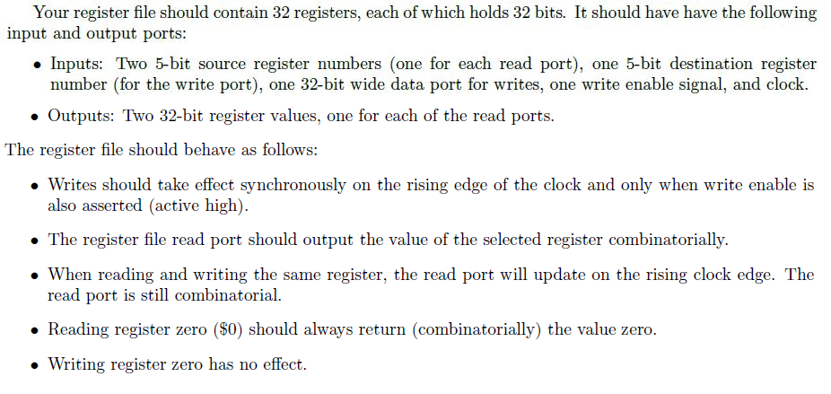
Your register file should contain 32 registers, each of which holds 32 bits. It should have have the following input and output ports: Inputs: Two 5-bit source register numbers (one for each read port), one 5-bit destination register number (for the write port), one 32-bit wide data port for writes, one write enable signal, and clock. Outputs: Two 32-bit register values, one for each of the read ports. The register file should behave as follows: Writes should take effect synchronously on the rising edge of the clock and only when write enable is also asserted (active high). The register file read port should output the value of the selected register combinatorially. When reading and writing the same register, the read port will update on the rising clock edge. The read port is still combinatorial. Reading register zero ($0) should always return (combinatorially) the value zero. Writing register zero has no effect. Your register file should contain 32 registers, each of which holds 32 bits. It should have have the following input and output ports: Inputs: Two 5-bit source register numbers (one for each read port), one 5-bit destination register number (for the write port), one 32-bit wide data port for writes, one write enable signal, and clock. Outputs: Two 32-bit register values, one for each of the read ports. The register file should behave as follows: Writes should take effect synchronously on the rising edge of the clock and only when write enable is also asserted (active high). The register file read port should output the value of the selected register combinatorially. When reading and writing the same register, the read port will update on the rising clock edge. The read port is still combinatorial. Reading register zero ($0) should always return (combinatorially) the value zero. Writing register zero has no effectStep by Step Solution
There are 3 Steps involved in it
Step: 1

Get Instant Access to Expert-Tailored Solutions
See step-by-step solutions with expert insights and AI powered tools for academic success
Step: 2

Step: 3

Ace Your Homework with AI
Get the answers you need in no time with our AI-driven, step-by-step assistance
Get Started


