

Question
module top (hz100, reset, pb, ss7, ss6, ss5, ss4, ss3, ss2, ss1, ss0, left, right, red, green, blue); input hz100, reset; input [20:0] pb; output
module top (hz100, reset, pb, ss7, ss6, ss5, ss4, ss3, ss2, ss1, ss0, left, right, red, green, blue); input hz100, reset; input [20:0] pb; output [7:0] ss7, ss6, ss5, ss4, ss3, ss2, ss1, ss0, left, right; output red, green, blue;
wire [15:0] y;
decoder u4(.e(1'b1), .a(pb[3:0]), .y(y));
assign y = {left,right}; // for debugging
wire a,b,c,d,e,f,g; assign ss0[6:0] = {g,f,e,d,c,b,a}; // connect A-G to ss0
// Your segment decode statements go below. assign a = ~(y[1] & y[4] & y[11] & y[13]); // assign b = // assign c = // assign d = // assign e = // assign f = // assign g = endmodule
module decoder(e,a,y); input e; input [3:0] a; output [15:0] y;
wire [15:0] ypos; // ypos is the positively-asserted version of the output assign y = { e & a[3] & a[2] & a[1] & a[0], e & a[3] & a[2] & a[1] & ~a[0], e & a[3] & a[2] & ~a[1] & a[0], e & a[3] & a[2] & ~a[1] & ~a[0], e & a[3] & ~a[2] & a[1] & a[0], e & a[3] & ~a[2] & a[1] & ~a[0], e & a[3] & ~a[2] & ~a[1] & a[0], e & a[3] & ~a[2] & ~a[1] & ~a[0], e & ~a[3] & a[2] & a[1] & a[0], e & ~a[3] & a[2] & a[1] & ~a[0], e & ~a[3] & a[2] & ~a[1] & a[0], e & ~a[3] & a[2] & ~a[1] & ~a[0], e & ~a[3] & ~a[2] & a[1] & a[0], e & ~a[3] & ~a[2] & a[1] & ~a[0], e & ~a[3] & ~a[2] & ~a[1] & a[0], e & ~a[3] & ~a[2] & ~a[1] & ~a[0] }; endmodule
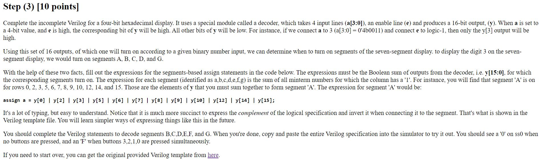
Step (3) [10 points] Complete the incomplete Verilog for a four-bit hexadecimal display. It uses a special module called a decoder, which takes 4 input lines (a[3:0]), an enable line (e) and produces a 16-bit output, (y). When a is set to a 4-bit value, and e is high, the corresponding bit of y will be high. All other bits of y will be low. For instance, if we connect a to 3 (a[3:0] = 0'460011) and connect e to logic-1, then only the y[3] output will be high. Using this set of 16 outputs, of which one will turn on according to a given binary number input, we can determine when to turn on segments of the seven-segment display. to display the digit 3 on the seven- segment display, we would turn on segments A, B, C, D, and G. With the help of these two facts, fill out the expressions for the segments-based assign statements in the code below. The expressions must be the Boolean sum of outputs from the decoder, i.e. y[15:0), for which the corresponding segments turn on. The expression for each segment (identified as a,b,c,d,e,f,g) is the sum of all minterm numbers for which the column has a 'l'. For instance, you will find that segment 'A' is on for rows 0, 2, 3, 5, 6, 7, 8, 9, 10, 12, 14, and 15. Those are the elements of y that you must sum together to form segment 'A'. The expression for segment 'A' would be: assign a = y[o] | y[2] | y[3] | y[5] | y[6] | y[7] | y[8] | y[9] | y[10] | y[12] | y[14] | y[15]; It's a lot of typing, but easy to understand. Notice that it is much more succinct to express the complement of the logical specification and invert it when connecting it to the segment. That's what is shown in the Verilog template file. You will learn simpler ways of expressing things like this in the future. You should complete the Verilog statements to decode segments B,C,D,E,F, and G. When you're done, copy and paste the entire Verilog specification into the simulator to try it out. You should see a 'O' on ss0 when no buttons are pressed, and an 'F' when buttons 3,2,1,0 are pressed simultaneously. If you need to start over, you can get the original provided Verilog template from here. Step (3) [10 points] Complete the incomplete Verilog for a four-bit hexadecimal display. It uses a special module called a decoder, which takes 4 input lines (a[3:0]), an enable line (e) and produces a 16-bit output, (y). When a is set to a 4-bit value, and e is high, the corresponding bit of y will be high. All other bits of y will be low. For instance, if we connect a to 3 (a[3:0] = 0'460011) and connect e to logic-1, then only the y[3] output will be high. Using this set of 16 outputs, of which one will turn on according to a given binary number input, we can determine when to turn on segments of the seven-segment display. to display the digit 3 on the seven- segment display, we would turn on segments A, B, C, D, and G. With the help of these two facts, fill out the expressions for the segments-based assign statements in the code below. The expressions must be the Boolean sum of outputs from the decoder, i.e. y[15:0), for which the corresponding segments turn on. The expression for each segment (identified as a,b,c,d,e,f,g) is the sum of all minterm numbers for which the column has a 'l'. For instance, you will find that segment 'A' is on for rows 0, 2, 3, 5, 6, 7, 8, 9, 10, 12, 14, and 15. Those are the elements of y that you must sum together to form segment 'A'. The expression for segment 'A' would be: assign a = y[o] | y[2] | y[3] | y[5] | y[6] | y[7] | y[8] | y[9] | y[10] | y[12] | y[14] | y[15]; It's a lot of typing, but easy to understand. Notice that it is much more succinct to express the complement of the logical specification and invert it when connecting it to the segment. That's what is shown in the Verilog template file. You will learn simpler ways of expressing things like this in the future. You should complete the Verilog statements to decode segments B,C,D,E,F, and G. When you're done, copy and paste the entire Verilog specification into the simulator to try it out. You should see a 'O' on ss0 when no buttons are pressed, and an 'F' when buttons 3,2,1,0 are pressed simultaneously. If you need to start over, you can get the original provided Verilog template from hereStep by Step Solution
There are 3 Steps involved in it
Step: 1

Get Instant Access to Expert-Tailored Solutions
See step-by-step solutions with expert insights and AI powered tools for academic success
Step: 2

Step: 3
Ace Your Homework with AI
Get the answers you need in no time with our AI-driven, step-by-step assistance
Get Started
Modern Datalog Engines In Databases
Authors: Bas Ketsman ,Paraschos Koutris
1st Edition
1638280428, 978-1638280422