Answered step by step
Verified Expert Solution
Question
1 Approved Answer
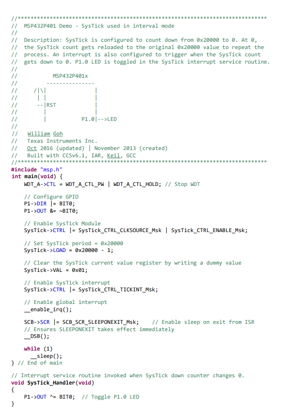
*********// // MSP432P401 Demo - SysTick used in interval mode // Description: SysTick is configured to count down from 0x20000 to 0. At 0,


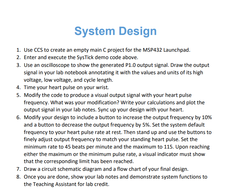
*********// // MSP432P401 Demo - SysTick used in interval mode // Description: SysTick is configured to count down from 0x20000 to 0. At 0, the SysTick count gets reloaded to the original 0x20000 value to repeat the // process. An interrupt is also configured to trigger when the SysTick count // gets down to 0. P1.0 LED is toggled in the SysTick interrupt service routine. MSP432P401x ZIN || --|RST // // //** #include "msp.h" William Goh Texas Instruments Inc. Oct 2016 (updated) | November 2013 (created) Built with CCSv6.1, IAR, Keil, GCC int main(void) { WDT_A->CTL = WDT_A_CTL_PW | WDT_A_CTL_HOLD; // Stop WDT } // Configure GPIO P1->DIR | BITO; P1->OUT &= ~BITO; P1.0|-->LED // Enable SysTick Module SysTick->CTRL |= SysTick_CTRL_CLKSOURCE_Msk | SysTick_CTRL_ENABLE_Msk; // Set SysTick period = 0x20000 SysTick-> LOAD = 0x20000 - 1; // Clear the SysTick current value register by writing a dummy value SysTick->VAL=0x01; // Enable SysTick interrupt SysTick->CTRL |= SysTick_CTRL_TICKINT_Msk; // Enable global interrupt _enable_irq(); ************ while (1) __sleep(); } // End of main SCB->SCR |= SCB SCR_SLEEPONEXIT_Msk; // Enable sleep on exit from ISR // Ensures SLEEPONEXIT takes effect immediately _DSB (); // Interrupt service routine invoked when SysTick down counter changes 0. void SysTick_Handler (void) { P1->OUT ^= BIT0; // Toggle P1.0 LED System Design 1. Use CCS to create an empty main C project for the MSP432 Launchpad. 2. Enter and execute the SysTick demo code above. 3. Use an oscilloscope to show the generated P1.0 output signal. Draw the output signal in your lab notebook annotating it with the values and units of its high voltage, low voltage, and cycle length. 4. Time your heart pulse on your wrist. 5. Modify the code to produce a visual output signal with your heart pulse frequency. What was your modification? Write your calculations and plot the output signal in your lab notes. Sync up your design with your heart. 6. Modify your design to include a button to increase the output frequency by 10% and a button to decrease the output frequency by 5%. Set the system default frequency to your heart pulse rate at rest. Then stand up and use the buttons to finely adjust output frequency to match your standing heart pulse. Set the minimum rate to 45 beats per minute and the maximum to 115. Upon reaching either the maximum or the minimum pulse rate, a visual indicator must show that the corresponding limit has been reached. 7. Draw a circuit schematic diagram and a flow chart of your final design. 8. Once you are done, show your lab notes and demonstrate system functions to the Teaching Assistant for lab credit.
Step by Step Solution
There are 3 Steps involved in it
Step: 1
The skin friction coefficient Cf for a laminar boundary ...
Get Instant Access to Expert-Tailored Solutions
See step-by-step solutions with expert insights and AI powered tools for academic success
Step: 2

Step: 3

Ace Your Homework with AI
Get the answers you need in no time with our AI-driven, step-by-step assistance
Get Started


