

Answered step by step
Verified Expert Solution
Question
1 Approved Answer
My number is 45678 and write full solution for this task. Please dont write in which part what should I do. I need full solution.
My number is 45678 and write full solution for this task. Please dont write in which part what should I do. I need full solution.
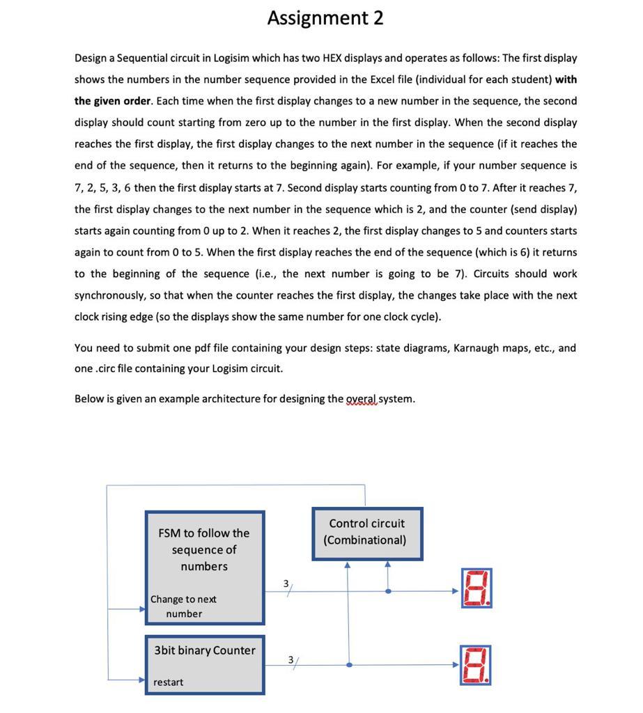
Design a Sequential circuit in Logisim which has two HEX displays and operates as follows: The first display shows the numbers in the number sequence provided in the Excel file (individual for each student) with the given order. Each time when the first display changes to a new number in the sequence, the second display should count starting from zero up to the number in the first display. When the second display reaches the first display, the first display changes to the next number in the sequence (if it reaches the end of the sequence, then it returns to the beginning again). For example, if your number sequence is 7, 2, 5, 3,6 then the first display starts at 7. Second display starts counting from 0 to 7 . After it reaches 7, the first display changes to the next number in the sequence which is 2, and the counter (send display) starts again counting from 0 up to 2 . When it reaches 2 , the first display changes to 5 and counters starts again to count from 0 to 5 . When the first display reaches the end of the sequence (which is 6 ) it returns to the beginning of the sequence (i.e., the next number is going to be 7). Circuits should work synchronously, so that when the counter reaches the first display, the changes take place with the next clock rising edge (so the displays show the same number for one clock cycle). You need to submit one pdf file containing your design steps: state diagrams, Karnaugh maps, etc., and one .circ file containing your Logisim circuit. Below is given an example architecture for designing the overal system. Design a Sequential circuit in Logisim which has two HEX displays and operates as follows: The first display shows the numbers in the number sequence provided in the Excel file (individual for each student) with the given order. Each time when the first display changes to a new number in the sequence, the second display should count starting from zero up to the number in the first display. When the second display reaches the first display, the first display changes to the next number in the sequence (if it reaches the end of the sequence, then it returns to the beginning again). For example, if your number sequence is 7, 2, 5, 3,6 then the first display starts at 7. Second display starts counting from 0 to 7 . After it reaches 7, the first display changes to the next number in the sequence which is 2, and the counter (send display) starts again counting from 0 up to 2 . When it reaches 2 , the first display changes to 5 and counters starts again to count from 0 to 5 . When the first display reaches the end of the sequence (which is 6 ) it returns to the beginning of the sequence (i.e., the next number is going to be 7). Circuits should work synchronously, so that when the counter reaches the first display, the changes take place with the next clock rising edge (so the displays show the same number for one clock cycle). You need to submit one pdf file containing your design steps: state diagrams, Karnaugh maps, etc., and one .circ file containing your Logisim circuit. Below is given an example architecture for designing the overal systemStep by Step Solution
There are 3 Steps involved in it
Step: 1

Get Instant Access to Expert-Tailored Solutions
See step-by-step solutions with expert insights and AI powered tools for academic success
Step: 2

Step: 3
Ace Your Homework with AI
Get the answers you need in no time with our AI-driven, step-by-step assistance
Get Started
Database And Expert Systems Applications 22nd International Conference Dexa 2011 Toulouse France August/September 2011 Proceedings Part 1 Lncs 6860
Authors: Abdelkader Hameurlain ,Stephen W. Liddle ,Klaus-Dieter Schewe ,Xiaofang Zhou
2011th Edition