

Answered step by step
Verified Expert Solution
Question
1 Approved Answer
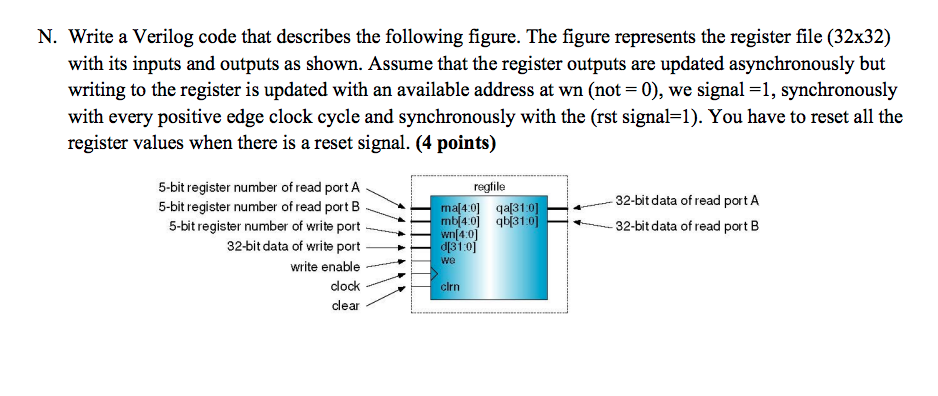
N. Write a Verilog code that describes the following figure. The figure represents the register file (32x32) with its inputs and outputs as shown. Assume
Step by Step Solution
There are 3 Steps involved in it
Step: 1

Get Instant Access to Expert-Tailored Solutions
See step-by-step solutions with expert insights and AI powered tools for academic success
Step: 2

Step: 3
Ace Your Homework with AI
Get the answers you need in no time with our AI-driven, step-by-step assistance
Get Started
Advanced Database Systems
Authors: Carlo Zaniolo, Stefano Ceri, Christos Faloutsos, Richard T. Snodgrass, V.S. Subrahmanian, Roberto Zicari
1st Edition
155860443X, 978-1558604438