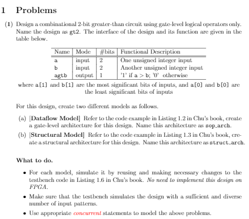
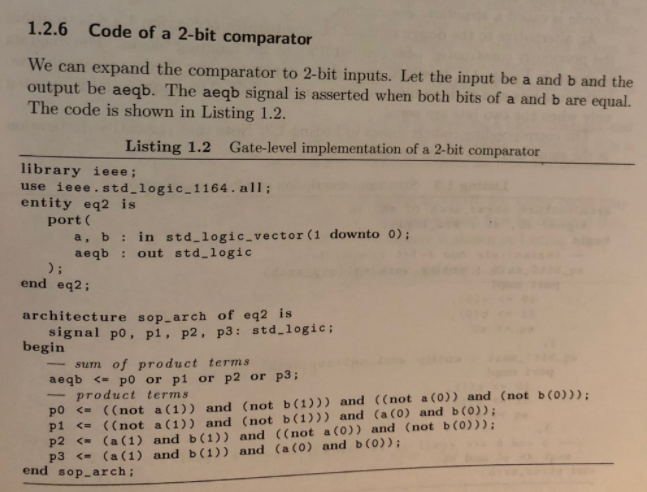
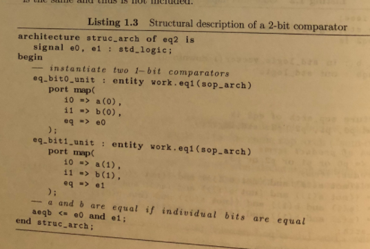
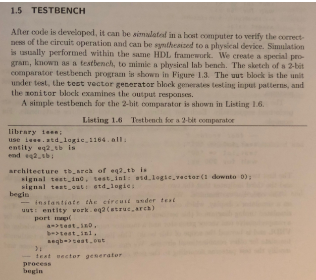
Name Mode a b 2 2 1 Problems (1) Design a combinational 2-bit greater than circuit using gate-level logical operators only. Name the design as gt2. The interface of the design and its function are given in the table below. #bits Functional Description input One unsigned integer input. input Another unsigned integer input agtb output 1 'l' if a > b; 'O' otherwise where a[1] and b[1] are the most significant bits of inputs, and a[0] and b[0] are the least significant bits of inputs For this design, create two different models as follows. (a) Dataflow Model] Refer to the code example in Listing 1.2 in Chu's book, create a gate-level architecture for this design. Name this architecture as sop_arch. (b) Structural Model] Refer to the code example in Listing 1.3 in Chu's book, cre ate a structural architecture for this design. Name this architecture as struct-arch. What to do. . For each model, simulate it by reusing and making necessary changes to the testbench code in Listing 1.6 in Chu's book. No need to implement this design on FPGA. Make sure that the testbench simulates the design with a sufficient and diverse number of input patterns. Use appropriate concurrent statements to model the above problems. 1.2.6 Code of a 2-bit comparator We can expand the comparator to 2-bit inputs. Let the input be a and b and the output be aeqb. The aeqb signal is asserted when both bits of a and b are equal. The code is shown in Listing 1.2. Listing 1.2 Gate-level implementation of a 2-bit comparator library ieee; use ieee.std_logic_1164. all; entity eq2 is port a, b: in std_logic_vector (1 downto 0); aeqb : out std_logic end eq2; architecture sop-arch of eq2 is signal po, pi, P2, P3: std_logic; begin sum of product terms aeqb a(0) 11 => (0), eq => 0 eq-biti unit : entity work.eqi (sop-arch) port map 10 => a(1) 11 -> b(1), eq => 1 - a and b are equal if individual bits are equal aeqb test_ino, br>test_ini, aeqb=>test_out test vector generator process begin Name Mode a b 2 2 1 Problems (1) Design a combinational 2-bit greater than circuit using gate-level logical operators only. Name the design as gt2. The interface of the design and its function are given in the table below. #bits Functional Description input One unsigned integer input. input Another unsigned integer input agtb output 1 'l' if a > b; 'O' otherwise where a[1] and b[1] are the most significant bits of inputs, and a[0] and b[0] are the least significant bits of inputs For this design, create two different models as follows. (a) Dataflow Model] Refer to the code example in Listing 1.2 in Chu's book, create a gate-level architecture for this design. Name this architecture as sop_arch. (b) Structural Model] Refer to the code example in Listing 1.3 in Chu's book, cre ate a structural architecture for this design. Name this architecture as struct-arch. What to do. . For each model, simulate it by reusing and making necessary changes to the testbench code in Listing 1.6 in Chu's book. No need to implement this design on FPGA. Make sure that the testbench simulates the design with a sufficient and diverse number of input patterns. Use appropriate concurrent statements to model the above problems. 1.2.6 Code of a 2-bit comparator We can expand the comparator to 2-bit inputs. Let the input be a and b and the output be aeqb. The aeqb signal is asserted when both bits of a and b are equal. The code is shown in Listing 1.2. Listing 1.2 Gate-level implementation of a 2-bit comparator library ieee; use ieee.std_logic_1164. all; entity eq2 is port a, b: in std_logic_vector (1 downto 0); aeqb : out std_logic end eq2; architecture sop-arch of eq2 is signal po, pi, P2, P3: std_logic; begin sum of product terms aeqb a(0) 11 => (0), eq => 0 eq-biti unit : entity work.eqi (sop-arch) port map 10 => a(1) 11 -> b(1), eq => 1 - a and b are equal if individual bits are equal aeqb test_ino, br>test_ini, aeqb=>test_out test vector generator process begin


