Question: Name (please print): Total Points: (last) first 8. [40 points] Pictured at right is a circuit consisting of 6 resistors and 3 batteries. Suppose the
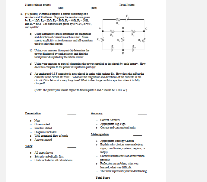
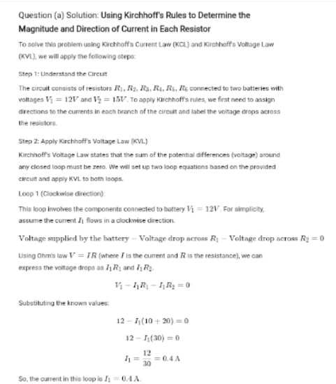
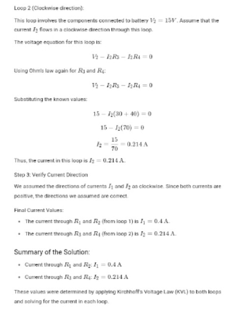
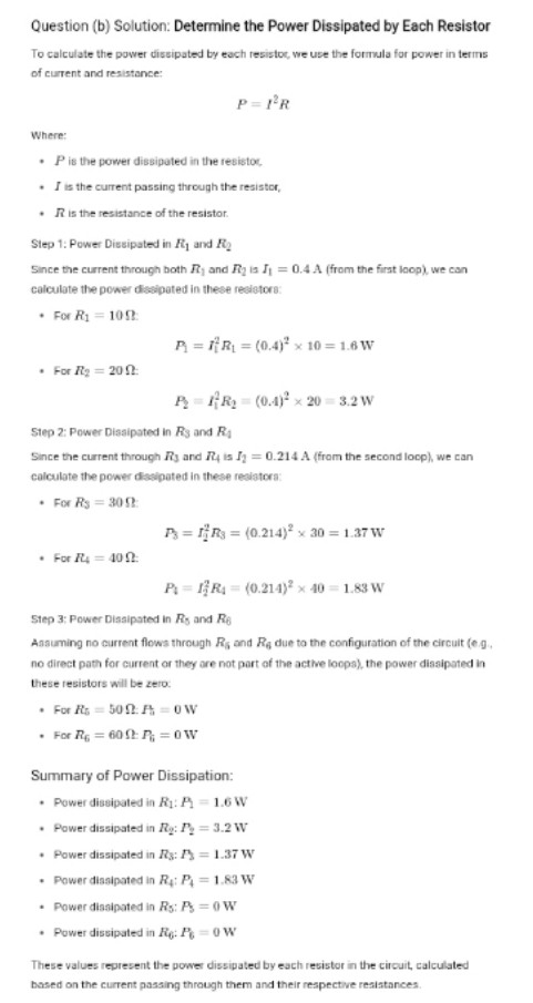
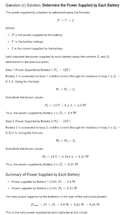
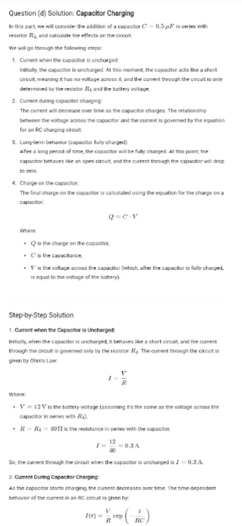
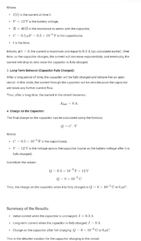
Name (please print): Total Points: (last) first 8. [40 points] Pictured at right is a circuit consisting of 6 resistors and 3 batteries. Suppose the resistors are given by Ry = 108. R- =200, R. =300, R = 400, R. = 502 and Ry= 600. The batteries are given by & =12V, &=9V, and = =18V. 2) Using Kirchhoff's rules determine the magnitude and direction of current in each resistor. Make sure to explicitly write down any and all equations used to solve this circuit. b) Using your answers from part (2) determine the power dissipated by each resistor, and find the total power dissipated by the whole circuit () Using your answers to part (2) determine the power supplied to the circuit by each battery. How does this compare to the power dissipated in part (b)? d) An uncharged 0.5 F capacitor is nowplaced in series with resistor F4. How does this affect the currents in the circuit at t = 0:? What are the magnitude and directions of the currents in the circuit if it is let to sit a very long time? What is the charge on this capacitor when it is fully charged? (Note: the power you should expect to find in parts b and c should be 3.883 W.) Presentation Accuracy 0 Neat Correct Answers Givens noted Appropriate Sig. Figs. Problem stated Correct and conventional units o Diagrams included o Well organized flow of work Metacognition Answers noted Appropriate Strategy Chosen Work Explain why choices were made (e.g. signs, coordinates, systems, regions, or All steps shown loops) o Solved symbolically first Check reasonableness of answer when Units included in all calculations possible Reflection on problem; what you learned, what was difficult The work represents your understanding Total ScoreQuestion (a) Solution: Using Kirchhoff's Rules to Determine the Magnitude and Direction of Current in Each Resistor To solve this problem using Kirchhoff's Current Law (KCL) and Kirchhoff's Voltage Law (KVL). we will apply the following steps Step 1: Understand the Circuit The circuit consists of resistors I, No, Ra. It. Iis, It's connected to two batteries with voltages Vi = 121/ and Vy = 151, To apply Kirchhoff's rules, we first need to assign directions to the currents in each branch of the circuit and label the voltage drops across the resistors. Step 2: Apply Kirchhoff's Voltage Law (KVL) Kirchhoff's Voltage Law states that the sum of the potential differences (voltage) around any closed loop must be zero. We will set up two loop equations based on the provided circuit and apply KVL to both loops. Loop 1 (Clockwise direction) This loop involves the components connected to battery Vi = 12V. For simplicity. assume the current Ji flows in a clockwise direction. Voltage supplied by the battery - Voltage drop across 1 - Voltage drop across Ry = 0 Using Ohm's low V = / R (where I is the current and R is the resistance), we can express the voltage drops as J R, and / Re. Substituting the known values. 12 - 7 (10 + 20) = 0 12 - 5 (20) = 0 12 11= 30 =04A So, the current in this loop is /1 = 0.4ALoop 2 (Clockwise direction): This loop involves the components connected to battery 19 = 15V. Assume that the current ly flows in a clockwise direction through this loop. The voltage equation for this loop is: 1- DR- MRA = 0 Using Ohm's law again for Ry and RA: Substituting the known values: 15 - 12(30 + 40) =0 15 - 1(70) = 0 15 =0.214 A 70 Thus, the current in this loop is It = 0.214 A. Step 3: Verily Current Direction We assumed the directions of currents Jj and /2 as clockwise. Since both currents are positive, the directions we assumed are correct Final Current Values: . The current through R, and Ry (from loop 1) is ]] = 0.4 A . The current through Ry and Ry (from loop 2) is 12 = 0.214 A Summary of the Solution: . Current through R and Ry: ]] = 0.4 A . Current through Ity and Ry: 19 = 0.214 A These values were determined by applying Kirchhoff's Voltage Law (KVL) to both loops and solving for the current in each loopQuestion (b) Solution: Determine the Power Dissipated by Each Resistor To calculate the power dissipated by each resistor, we use the formula for power in terms of current and resistance: P =IR Where: . P is the power dissipated in the resistor . I is the current passing through the resistor, . R is the resistance of the resistor. Step 1: Power Dissipated in /j and Fy Since the current through both R, and Ry is J = 0.4 A (from the first loop), we can calculate the power dissipated in these resistors: . For R1 = 10 0 A = NR1 = (0.4)3 x 10 = 1.6 W . For /to = 20 0 R = PR, = (0.1)* * 20 = 3.2 W Step 2: Power Dissipated in Rs and Ra Since the current through Ry and 1 is Jy = 0.214 A (from the second loop), we can calculate the power dissipated in these resistors: . For RS = 30 0 P = IRs = (0.214)# x 20 = 1.37 W . For /4 = 40 0 PI = 17RA = (0.214)# x 40 = 1.83 W Step 3; Power Dissipated in Ry and Re Assuming no current flows through Rs and Ry due to the configuration of the circuit (e.g, no direct path for current or they are not part of the active loops), the power dissipated in these resistors will be zero. . For its = 50 0. A = OW . For Ro = 60 0: R; = 0 W Summary of Power Dissipation: . Power dissipated in R1: A = 1.6 W . Power dissipated in Ry: /) = 3.2 W . Power dissipated in 173: /) = 1.37 W . Power dissipated in Ry: P) = 1.83 W . Power dissipated in Rs: As = 0 W . Power dissipated in Ro: 1% = 0 W These values represent the power dissipated by each resistor in the circuit, calculated based on the current passing through them and their respective resistances.Question (c) Solution: Determine the Power Supplied by Each Battery The power supplied by a battery is calculated using the formula: P = VxI Where: . P is the power supplied by the battery, . V is the battery vollage, . I is the current supplied by the battery. Let's calculate the power supplied by each battery using the currents ], and I? determined in the previous parts. Slep 1: Power Supplied by Battery 1 (V = 121) Battery 1 is connected to loop 1, and the current through the resistors in loop 1 is /1 = 0.4 A. Using the formula: A=Vix Substitute the known values: A = 12 V x 04A = 4.8W Thus, the power supplied by Battery 1 Is P = 4.8 W Step 2: Power Supplied by Battery 2 (12 = 151) Battery 2 is connected to loop 2, and the current through the resistors in loop 2 is /_ = 0.214 A. Using the formula: Substitute the known values: A = 15V x 0.214 A = 3.21 W Thus, the power supplied by Battery 2 Is By = 3.21 W. Summary of Power Supplied by Each Battery: . Power supplied by Battery 1 (12V): A = 4.8 W . Power supplied by Battery 2 (15V): P; = 3.21 W The total power supplied by the batteries is the sum of the individual powers: Aul = A+1=48W +3.21 W =8.01 W This is the total power supplied by both batteries in the circuit.Question (d) Solution: Capacitor Charging In this part, we will consider the addition of a capacitor C' = 0.5 of in series with resistor Ry, and calculate the effects on the circuit. We will go through the following steps: 1. Current when the capacitor is uncharged Initially, the capacitor is uncharged. At this moment, the capacitor acts like a short circuit, meaning it has no voltage across it, and the current through the circuit is only determined by the resistor 17 and the battery voltage 2. Current during capacitor charging The current will decrease over time as the capacitor charges. The relationship between the voltage across the capacitor and the current is governed by the equation for an RC charging circuit. 3. Long-term behavior (capacitor fully charged): After a long period of time, the capacitor will be fully charged. At this point, the capacitor behaves like an open circuit, and the current through the capacitor will drop to zero. 4. Charge on the capacitor: The final charge on the capacitor is calculated using the equation for the charge on a capacitor Q =C. V Where: . Q is the charge on the capacitor, . C is the capacitance, . V/ is the voltage across the capacitor (which after the capacitor is fully charged. is equal to the voltage of the battery). Step-by-Step Solution 1. Current when the Capacitor is Uncharged: Initially, when the capacitor is uncharged, it behaves like a short circuit, and the current through the circuit is governed only by the resistor Ry. The current through the circuit is given by Ohmi's Low. I = R Where: . V = 12 V is the battery voltage (assuming It's the same as the voltage across the capacitor in series with R4). . R = Ry = 40 1 is the resistance in series with the capacitor. 1 = 12 =03A 40 So, the current through the circuit when the capacitor is uncharged is / = 0.3 A. 2. Current During Capacitor Charging: As the capacitor starts charging, the current decreases over time. The time dependent behavior of the current in an RC circuit is given by: 7(t) = exp R RCWhere: . I () is the current at time & . V = 12 V is the battery voltage, . R = 40 01 is the resistance in series with the capacitor, . C=0.5 /F = 0.5 x 10 Fie the capacitance, . f is the time. Initially, at * = 0, the current is maximum and equal to 0.3 A (as calculated earlier). Over time, as the capacitor charges, the current will decrease exponentially, and eventually, the current will drop to zero once the capacitor is fully charged. 3. Long-Term Behavior (Capacitor Fully Charged): After a long period of time, the capacitor will be fully charged and behave like an open circuit In this state, the current through the capacitor will be zero because the capacitor will block any further current flow. Thus, after a long time, the current in the circuit becomes: and = 0 A 4. Charge on the Capacitor: The final charge on the capacitor can be calculated using the formula: Q =C. V Where: . C =0.5 x 10 F is the capacitance. . V = 12 V is the voltage across the capacitor (same as the battery voltage after it is fully charged). Substitute the values: Q = 0.5 x 10 'F x 12 V Q=6 x 10 c Thus, the charge on the capacitor when it is fully charged is Q = 6 x 10-C or 6 pC. Summary of the Results: . Initial current when the capacitor is uncharged J = 0.3 A . Long-term current when the capacitor is fully charged / = 0 A . Charge on the capacitor after full charging: Q = 6 x 10-" C or 6 JC This is the detailed solution for the capacitor charging in the circuit
Step by Step Solution
There are 3 Steps involved in it
1 Expert Approved Answer
Step: 1 Unlock
Question Has Been Solved by an Expert!
Get step-by-step solutions from verified subject matter experts
Step: 2 Unlock
Step: 3 Unlock
Students Have Also Explored These Related Accounting Questions!