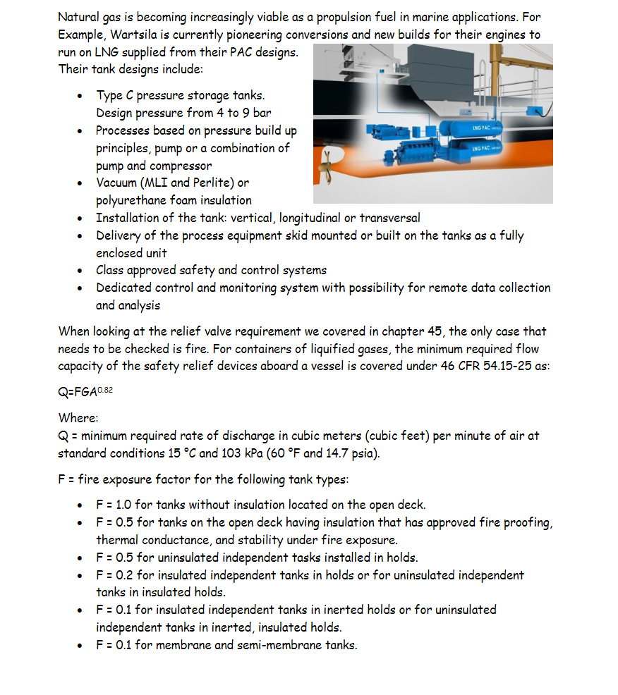
Natural gas is becoming increasingly viable as a propulsion fuel in marine applications. For Example, Wartsila is currently pioneering conversions and new builds for their enqines to run on LNG supplied from their PAC designs. Their tank designs include: - Type C pressure storage tanks. Design pressure from 4 to 9 bar - Processes based on pressure build up principles, pump or a combination of pump and compressor - Vacuum (MLI and Perlite) or polyurethane foam insulation - Installation of the tank: vertical, longitudinal or transversal - Delivery of the process equipment skid mounted or built on the tanks as a fully enclosed unit - Class approved safety and control systems - Dedicated control and monitoring system with possibility for remote data collection and analysis When looking at the relief valve requirement we covered in chapter 45 , the only case that needs to be checked is fire. For containers of liquified gases, the minimum required flow capacity of the safety relief devices aboard a vessel is covered under 46 CFR 54.15-25 as: Q=FGA0.82 Where: Q= minimum required rate of discharge in cubic meters (cubic feet) per minute of air at standard conditions 15C and 103kPa(60F and 14.7psia). F= fire exposure factor for the following tank types: - F=1.0 for tanks without insulation located on the open deck. - F=0.5 for tanks on the open deck having insulation that has approved fire proofing, thermal conductance, and stability under fire exposure. - F=0.5 for uninsulated independent tasks installed in holds. - F=0.2 for insulated independent tanks in holds or for uninsulated independent tanks in insulated holds. - F=0.1 for insulated independent tanks in inerted holds or for uninsulated independent tanks in inerted, insulated holds. - F=0.1 for membrane and semi-membrane tanks. G=(177/LC)(ZT/M) Where: L= latent heat of the material being vaporized at the relieving conditions, in Kcal/kg C= constant based on relation of specific heats ( k ), table $54.1525 (c) (if k is not known, C=.606) Z= compressibility factor of the gas at the relieving conditions (if not known, Z=1.0 ). T= temperature in degrees K=(273+ degrees C) at the relieving conditions (120% of the pressure at which the pressure relief valve is set). M= molecular weight of the product. We have been tasked by the naval architect to make sure that the relief valve is compliant with the CFR for the tanks shown in the picture. We know the following about the tank: a. 3.5 m diameter b. 20 meter length c. 5 Bar pressure The surface area is not stamped on the nameplate and need to make a reasonable estimate of the outside area. Write an "email" to the project manager with a detailed description explaining the problem, regulation, equations, variables, assumptions, and calculations. The goals are to: 1. State the problem 2. Determine the vapor release rate for which the valve must be sized 3. What is the relieving pressure for which the valve must be sized to be compliant with 46 CFR 54.15-5- Protective Devices (modifies UG-125). Natural gas is becoming increasingly viable as a propulsion fuel in marine applications. For Example, Wartsila is currently pioneering conversions and new builds for their enqines to run on LNG supplied from their PAC designs. Their tank designs include: - Type C pressure storage tanks. Design pressure from 4 to 9 bar - Processes based on pressure build up principles, pump or a combination of pump and compressor - Vacuum (MLI and Perlite) or polyurethane foam insulation - Installation of the tank: vertical, longitudinal or transversal - Delivery of the process equipment skid mounted or built on the tanks as a fully enclosed unit - Class approved safety and control systems - Dedicated control and monitoring system with possibility for remote data collection and analysis When looking at the relief valve requirement we covered in chapter 45 , the only case that needs to be checked is fire. For containers of liquified gases, the minimum required flow capacity of the safety relief devices aboard a vessel is covered under 46 CFR 54.15-25 as: Q=FGA0.82 Where: Q= minimum required rate of discharge in cubic meters (cubic feet) per minute of air at standard conditions 15C and 103kPa(60F and 14.7psia). F= fire exposure factor for the following tank types: - F=1.0 for tanks without insulation located on the open deck. - F=0.5 for tanks on the open deck having insulation that has approved fire proofing, thermal conductance, and stability under fire exposure. - F=0.5 for uninsulated independent tasks installed in holds. - F=0.2 for insulated independent tanks in holds or for uninsulated independent tanks in insulated holds. - F=0.1 for insulated independent tanks in inerted holds or for uninsulated independent tanks in inerted, insulated holds. - F=0.1 for membrane and semi-membrane tanks. G=(177/LC)(ZT/M) Where: L= latent heat of the material being vaporized at the relieving conditions, in Kcal/kg C= constant based on relation of specific heats ( k ), table $54.1525 (c) (if k is not known, C=.606) Z= compressibility factor of the gas at the relieving conditions (if not known, Z=1.0 ). T= temperature in degrees K=(273+ degrees C) at the relieving conditions (120% of the pressure at which the pressure relief valve is set). M= molecular weight of the product. We have been tasked by the naval architect to make sure that the relief valve is compliant with the CFR for the tanks shown in the picture. We know the following about the tank: a. 3.5 m diameter b. 20 meter length c. 5 Bar pressure The surface area is not stamped on the nameplate and need to make a reasonable estimate of the outside area. Write an "email" to the project manager with a detailed description explaining the problem, regulation, equations, variables, assumptions, and calculations. The goals are to: 1. State the problem 2. Determine the vapor release rate for which the valve must be sized 3. What is the relieving pressure for which the valve must be sized to be compliant with 46 CFR 54.15-5- Protective Devices (modifies UG-125)