

Question
Network Addressing St. Louis Serial Port: 192.168.41.17 /30 (Chicago) Ethernet Port: 192.100.44.1 /24 Workstation A: 192.100.44.80 /24 Nashville Serial Port 192.168.81.129 /30 (Chicago) Ethernet Port:
Network Addressing
| St. Louis Serial Port: 192.168.41.17 /30 (Chicago) Ethernet Port: 192.100.44.1 /24 Workstation A: 192.100.44.80 /24 | Nashville Serial Port 192.168.81.129 /30 (Chicago) Ethernet Port: 192.120.54.1 /24 Workstation C: 192.120.54.11 /24 |
| Chicago Serial Port: 192.168.41.18 /30 (St. Louis) Serial Port: 192.168.81.130 /30 (Nashville) Serial Port: 192.168.207.65 /30 (Memphis) Serial Port: 192.168.55.193 /30 (Kansas City) Ethernet Port: 192.110.73.1 /24 Workstation B: 192.110.73.22 /24 | Memphis Serial Port 192.168.207.66 /30 (Chicago) Ethernet Port: 192.130.64.1 /24 Workstation D: 192.130.64.41 /24
|
Networks
How many subnets exist on the above topology? Write the subnet address, subnet mask (dotted decimal), and give a descriptive name (note: answer for the whole topology shown above, even if your group has less than 5 routers).
| Subnet Address | Subnet Mask | Name |
|
|
|
|
|
|
|
|
|
|
|
|
|
|
|
|
|
|
|
|
|
|
|
|
|
|
|
|
|
|
|
|
|
|
|
|
|
|
|
|
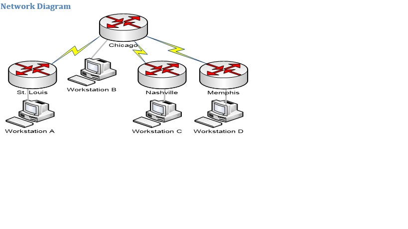
Physical Layout
The St. Louis, Nashville, Memphis, and Kansas City routers will connect to the Chicago router by a DTE/DCE cable. The Chicago router will provide clock synchronization to the other routers. It is necessary that the DCE end of the cable be connected to Chicago.
Once the routers Ethernet (or Fast Ethernet) port has been configured, you will disconnect your routers console cable and connect your workstation directly to a routers Ethernet port. Remember that direct PC to router connections must use a crossover cable. The correct IP address on your PC must also be configured for this connection to work correctly. At this point you will start a new Putty session using telnet as the connection type instead of serial.
Logical Layout and Router Configuration
All serial links between routers should be configured with PPP encapsulation and with the IP addresses listed above. Set the clock rate at 64000. Router Ethernet ports should be set with IP addresses as indicated. Workstations should be set with static IP addresses, and should set their default gateway to be the IP address of the directly connected router Ethernet interface.
To set an IP address on a router interface, use the syntax:
IP ADDRESS [IP ADDR] [SUBNET MASK]
Static routes should be added to each router to allow for communication between all devices. Remember, routes must be added to enable communications between networks not directly connected to each router. Routes should exist on both source and destination router to ensure return traffic works properly as well. The syntax for adding routes is:
IP ROUTE [DEST NET ADDR] [DEST NET MASK] [IP ADDR NEXT HOP]
Make sure all routers are given the appropriate hostname, and set the enable (encrypted) password of enable. The console password should be set to console. Configure and test telnet (VTY) access on each router with a password of telnet. Verify telnet can be used from workstations to routers and that each device can be pinged successfully from the other devices.
Commands Used
ENABLE SECRET, CLOCK RATE 64000, LINE CONSOLE, LINE VTY 0 4, INTERFACE, ENCAPSULATION PPP, LOGIN, IP ADDRESS, IP ROUTE, NO SHUTDOWN, SHOW IP ROUTE, SHOW IP INTERFACE BRIEF, SHOW CDP NEIGHBOR,SHOW INTERFACE, SHOW RUNNING-CONFIG, PING (used with no arguments)
Questions (40 points)
Please submit the answers or supporting evidence for these lab questions in a single Word document. Make sure that each question is clearly labeled and that each sub-item identifies which test or device it refers to. Cut and paste from your Putty logs or the Windows command window to answer specific questions. Cut and paste only the items relevant to the question into your submission document. Failure to do so will result in points deducted.
1-Show the routing tables for each router. Make sure the router is explicitly identified in your submission.
(10 points)
2-Show the results of several extended pings from the St. Louis Router to Nashville Router. Do 100 pings for each of the tests. For each of the three tests, record in the table the information found while doing the test. The purpose of this exercise is to observe how packet size affects the time to complete each set of 100 pings (5 points)
| Size of Ping Datagrams | Minimum | Maximum | Average | Time to Complete (use a watch or stopwatch to time) |
| 100 |
|
|
|
|
| 500 |
|
|
|
|
| 1000 |
|
|
|
|
3-Show the tracert results for the following tests. Use Window XPs tracert command from command prompt. (5 points)
a-Wkstn A to C
b-Wkstn B to C
c-Wkstn A to B
d-Wkstn B to D
e-Wkstn D to C
f-Wkstn D to A
4-Show the successful use of telnet from the Chicago router to both the St. Louis and Nashville routers. (5 points)
5-Show the running-config for all of your routers at the end of this exercise. (15 points assuming all requirements listed in configuration are correct)
answer all queastion please will rate
Network Diagram Chicag Workstation B St. Louis Nashville Memphis Workstation A Workstation C Workstation DStep by Step Solution
There are 3 Steps involved in it
Step: 1

Get Instant Access to Expert-Tailored Solutions
See step-by-step solutions with expert insights and AI powered tools for academic success
Step: 2

Step: 3
Ace Your Homework with AI
Get the answers you need in no time with our AI-driven, step-by-step assistance
Get Started
Data Visualization A Practical Introduction
Authors: Kieran Healy
1st Edition
0691181624, 978-0691181622