neural networks. backpropagation. i have posted a problem that contains steps and the answer. i am stuck on a few parts sk please explain each step in detail so i can thumbs up! if you just copy everything thst the answer says i will thumbs down. i am looking dor all the missing pieces to this problem. thanks!

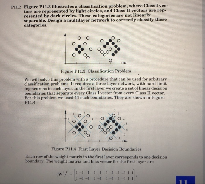
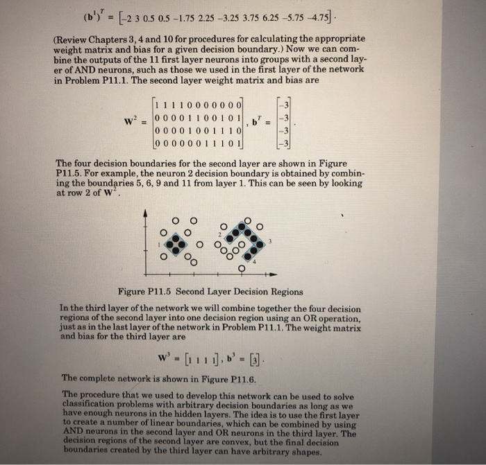
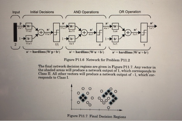
Figure P11.3 illustrates a classification problem, where Class I vec- tors are represented by light circles, and Class II vectors are rep- resented by dark circles. These categories are not linearly separable. Design a multilayer network to correctly classify these categories. P11.2 o O Figure P11.3 Classification Problem We will solve this problem with a procedure that can be used for arbitrary classification problems. It requires a three-layer network, with hard-limit- ing neurons in each layer. In the first layer we create a set oflinear decision boundaries that separate every Class I vector from every Class II vector. For this problem we used 11 such boundaries. They are shown in Figure P11.4 Figure P11.4 First Layer Decision Boundaries Each row of the weight matrix in the first layer corresponds to one decision boundary. The weight matrix and bias vector for the first layer are (b 2 3 0.5 0.5 -1.75 2.25 -3.25 3.75 6.25-5.75-4.75 (Review Chapters 3,4 and 10 for procedures for calculating the appropriate weight matrix and bias for a given decision boundary.) Now we can com- bine the outputs of the 11 first layer neurons into groups with a second lay- er of AND neurons, such as those we used in the first layer of the network in Problem P11.1. The second layer weight matrix and bias are 11 1 10 0 0 0 0 0 0 W",0 0 0 0 1 1 0 0 1 0 !!.br = |-3 -3 00001001 1 10 0 000001 110 1 The four decision boundaries for the second layer are shown in Figure P11.5. For example, the neuron 2 decision boundary is obtained by combin- ing the boundaries 5, 6, 9 and 11 from layer 1. This can be seen by looking at row 2 of w Figure P11.5 Second Layer Decision Regions In the third layer of the network we will combine together the four decision regions of the second layer into one decision region using an OR operation, just as in the last layer of the network in Problem P11.1. The weight matrix and bias for the third layer are The complete network is shown in Figure P11.6. The procedure that we used to develop this network can be used to solve classification problems with arbitrary decision boundaries as long as we have enough neurons in the hidden layers. The idea is to use the first layer to create a number of linear boundaries, which can be combined by using AND neurons in the second layer and OR neurons in the third layer. The decision regions of the second layer are convex, but the final decision boundaries created by the third layer can have arbitrary shapes AND Operations OR Operation Input Initial Decisions 4x1 2x1 4x 11 1 x4 11x2 11x1 4 x1 1! 4x1 11x1 4 1 x1 2 Figure P11.6 Network for Problem P11.2 The final network decision regions are given in Figure P11.7. Any vector in the shaded areas will produce a network output of 1, which corresponds to Class II. All other vectors will produce a network output of -1, which cor- responds to Class I. Figure P11.7 Final Decision Regions Figure P11.3 illustrates a classification problem, where Class I vec- tors are represented by light circles, and Class II vectors are rep- resented by dark circles. These categories are not linearly separable. Design a multilayer network to correctly classify these categories. P11.2 o O Figure P11.3 Classification Problem We will solve this problem with a procedure that can be used for arbitrary classification problems. It requires a three-layer network, with hard-limit- ing neurons in each layer. In the first layer we create a set oflinear decision boundaries that separate every Class I vector from every Class II vector. For this problem we used 11 such boundaries. They are shown in Figure P11.4 Figure P11.4 First Layer Decision Boundaries Each row of the weight matrix in the first layer corresponds to one decision boundary. The weight matrix and bias vector for the first layer are (b 2 3 0.5 0.5 -1.75 2.25 -3.25 3.75 6.25-5.75-4.75 (Review Chapters 3,4 and 10 for procedures for calculating the appropriate weight matrix and bias for a given decision boundary.) Now we can com- bine the outputs of the 11 first layer neurons into groups with a second lay- er of AND neurons, such as those we used in the first layer of the network in Problem P11.1. The second layer weight matrix and bias are 11 1 10 0 0 0 0 0 0 W",0 0 0 0 1 1 0 0 1 0 !!.br = |-3 -3 00001001 1 10 0 000001 110 1 The four decision boundaries for the second layer are shown in Figure P11.5. For example, the neuron 2 decision boundary is obtained by combin- ing the boundaries 5, 6, 9 and 11 from layer 1. This can be seen by looking at row 2 of w Figure P11.5 Second Layer Decision Regions In the third layer of the network we will combine together the four decision regions of the second layer into one decision region using an OR operation, just as in the last layer of the network in Problem P11.1. The weight matrix and bias for the third layer are The complete network is shown in Figure P11.6. The procedure that we used to develop this network can be used to solve classification problems with arbitrary decision boundaries as long as we have enough neurons in the hidden layers. The idea is to use the first layer to create a number of linear boundaries, which can be combined by using AND neurons in the second layer and OR neurons in the third layer. The decision regions of the second layer are convex, but the final decision boundaries created by the third layer can have arbitrary shapes AND Operations OR Operation Input Initial Decisions 4x1 2x1 4x 11 1 x4 11x2 11x1 4 x1 1! 4x1 11x1 4 1 x1 2 Figure P11.6 Network for Problem P11.2 The final network decision regions are given in Figure P11.7. Any vector in the shaded areas will produce a network output of 1, which corresponds to Class II. All other vectors will produce a network output of -1, which cor- responds to Class I. Figure P11.7 Final Decision Regions


