Question
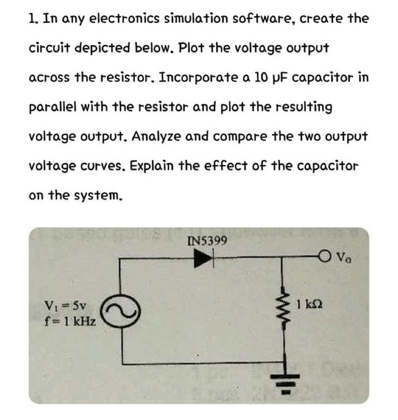
1. In any electronics simulation software, create the circuit depicted below. Plot the voltage output across the resistor. Incorporate a 10 pF capacitor in

1. In any electronics simulation software, create the circuit depicted below. Plot the voltage output across the resistor. Incorporate a 10 pF capacitor in parallel with the resistor and plot the resulting voltage output. Analyze and compare the two output voltage curves. Explain the effect of the capacitor on the system. V = Sv f = 1 kHz IN5399 O Vo 1 km2
Step by Step Solution
3.46 Rating (156 Votes )
There are 3 Steps involved in it
Step: 1
1 Circuit without the capacitor In the circuit without the capacitor the voltage output across the resistor will be determined solely by the resistanc...
Get Instant Access to Expert-Tailored Solutions
See step-by-step solutions with expert insights and AI powered tools for academic success
Step: 2

Step: 3

Ace Your Homework with AI
Get the answers you need in no time with our AI-driven, step-by-step assistance
Get StartedRecommended Textbook for
Foundations Of Finance
Authors: Arthur J. Keown, John H. Martin, J. William Petty
9th Edition
978-0134083285, 134083288, 978-0134084015
Students also viewed these Finance questions
Question
Answered: 1 week ago
Question
Answered: 1 week ago
Question
Answered: 1 week ago
Question
Answered: 1 week ago
Question
Answered: 1 week ago
Question
Answered: 1 week ago
Question
Answered: 1 week ago
Question
Answered: 1 week ago
Question
Answered: 1 week ago
Question
Answered: 1 week ago
Question
Answered: 1 week ago
Question
Answered: 1 week ago
Question
Answered: 1 week ago
Question
Answered: 1 week ago
Question
Answered: 1 week ago
Question
Answered: 1 week ago
Question
Answered: 1 week ago
Question
Answered: 1 week ago
Question
Answered: 1 week ago
Question
Answered: 1 week ago
Question
Answered: 1 week ago
Question
Answered: 1 week ago
View Answer in SolutionInn App


