Answered step by step
Verified Expert Solution
Link Copied!

Question

1 Approved Answer

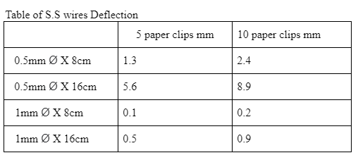
NO NEED EXPERIMENT ANSWER THE QUESTION WITH DATA, DISCUSS, AND CONCLUDE YOUR RESULT. Table of S.S wires Deflection begin{tabular}{|l|l|l|} hline & multicolumn{1}{|c|}{5 paper clips mm}

NO NEED EXPERIMENT

ANSWER THE QUESTION WITH DATA, DISCUSS, AND CONCLUDE YOUR RESULT.
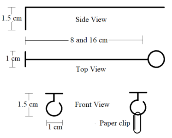
image text in transcribedimage text in transcribedimage text in transcribedimage text in transcribed

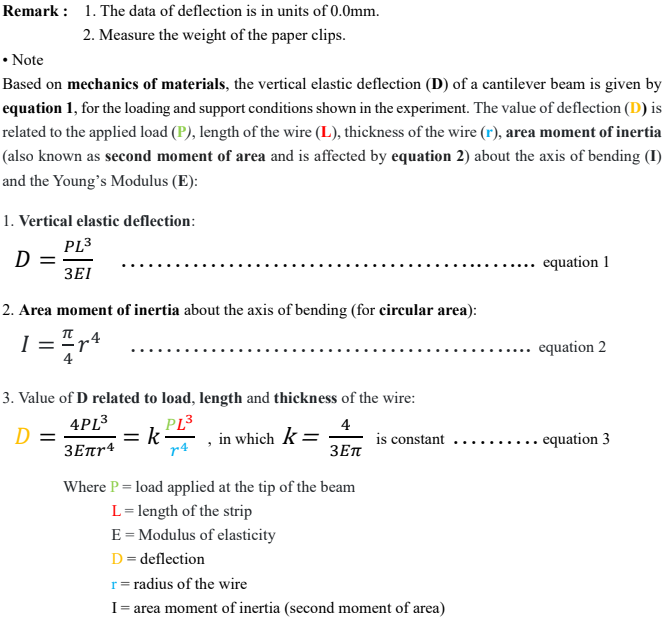
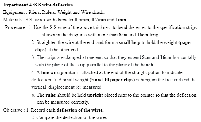
Table of S.S wires Deflection \begin{tabular}{|l|l|l|} \hline & \multicolumn{1}{|c|}{5 paper clips mm} & 10 paper clips mm \\ \hline 0.5mm8cm & 1.3 & 2.4 \\ \hline 0.5mm16cm & 5.6 & 8.9 \\ \hline 1mm8cm & 0.1 & 0.2 \\ \hline 1mm16cm & 0.5 & 0.9 \\ \hline \end{tabular} Remark: 1. The data of deflection is in units of 0.0mm. 2. Measure the weight of the paper clips. - Note Based on mechanics of materials, the vertical elastic deflection (D) of a cantilever beam is given by equation 1, for the loading and support conditions shown in the experiment. The value of deflection (D) is related to the applied load (P), length of the wire (L), thickness of the wire (r), area moment of inertia (also known as second moment of area and is affected by equation 2) about the axis of bending (I) and the Young's Modulus (E): 1. Vertical elastic deflection: D=3EIPL3 equation 1 2. Area moment of inertia about the axis of bending (for circular area): I=4r4 equation 2 3. Value of D related to load, length and thickness of the wire: D=3Er44PL3=kr4PL3, in which k=3E4 is constant . equation 3 Where P= load applied at the tip of the beam L= length of the strip E= Modulus of elasticity D= deflection r= radius of the wire I= area moment of inertia (second moment of area) eriment 4 :S.S wire deflection pment : Pliers, Rulers, Weight and Wire chuck. erials : S.S. wires with diameter 0.5mm,0.7mm and 1mm. cedure : 1. Use the S.S wire of the above thickness to bend the wires to the specification strips shown in the diagrams with more than 8cm and 16cm long. 2. Straighten the wire at the end, and form a small loop to hold the weight (paper clips) at the other end. 3. The strips are clamped at one end so that they extend 8cm and 16cm horizontally, with the plane of the strip parallel to the plane of the bench. 4. A fine wire pointer is attached at the end of the straight potion to indicate deflection. 5. A small weight ( 5 and 10 paper clips) is hung on the free end and the vertical displacement (d) measured. 6. The ruler should be held upright placed next to the pointer so that the deflection can be measured correctly. 1. Record each deflection of the wires. 2. Compare the deflection of the wires

Step by Step Solution

There are 3 Steps involved in it

Step: 1

blur-text-image

Get Instant Access to Expert-Tailored Solutions

See step-by-step solutions with expert insights and AI powered tools for academic success

Step: 2

blur-text-image

Step: 3

blur-text-image

Ace Your Homework with AI

Get the answers you need in no time with our AI-driven, step-by-step assistance

Get Started

Recommended Textbook for

Fundamentals Of Database Systems

Authors: Ramez Elmasri, Shamkant B. Navathe

7th Edition Global Edition

1292097612, 978-1292097619

More Books

Students also viewed these Databases questions

Question

What is the most important part of any HCM Project Map and why?

Answered: 1 week ago