

Question
note ****** its one question but with multiple requirements , can't be solved separately , thanks for the understanding because some experts keep saying they
note ****** its one question but with multiple requirements , can't be solved separately , thanks for the understanding because some experts keep saying they can't solve more than a question due to the guidelines , again *** its one question but with multiple requirements ****
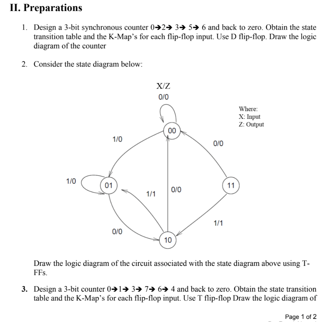
II. Preparations 1. Design a 3-bit synchronous counter 02+ 3+ 5+ 6 and back to zero. Obtain the state transition table and the K-Map's for each flip-flop input. Use D flip-flop. Draw the logic diagram of the counter 2. Consider the state diagram below: X/Z 0/0 Where: X: Input Z: Output 00 1/0 0/0 1/0 01 11 0/0 1/1 1/1 0/0 10 Draw the logic diagram of the circuit associated with the state diagram above using T- FFs. 3. Design a 3-bit counter 0+1= 376 4 and back to zero. Obtain the state transition table and the K-Map's for each flip-flop input. Use T flip-flop Draw the logic diagram of Page 1 of 2 the counter. Show that when binary states 010 and 101 are considered as don't care conditions, the counter may not operate properly (explain why) and find a way to correct the design. III. Lab work In this experiment: Setup the circuit in 1 using the Logisim software. Setup the circuit in 2 using the Logisim software. Setup the circuit in 3 using the Logisim softwareStep by Step Solution
There are 3 Steps involved in it
Step: 1

Get Instant Access to Expert-Tailored Solutions
See step-by-step solutions with expert insights and AI powered tools for academic success
Step: 2

Step: 3
Ace Your Homework with AI
Get the answers you need in no time with our AI-driven, step-by-step assistance
Get Started
SQL FOR BEGINNERS THE FUNDAMENTAL LANGUAGE FOR DATA SCIENCE TO MASTERING DATABASES AN ESSENTIAL GUIDE YOU CANNOT MISS TO LEARN SQL IN 7 DAYS OR LESS WITH HANDS ON PROJECTS
Authors: ERICK THOMPSON
1st Edition
B08KGT7GG2, 979-8686327658