

Answered step by step
Verified Expert Solution
Question
1 Approved Answer
Note that 0000 is used to reset stage. It is different from the question on book. Truth table with 8, 4, -2, -1 code as
Note that "0000" is used to reset stage. It is different from the question on book.
Truth table with 8, 4, -2, -1 code as input and normal BCD code as output is given.
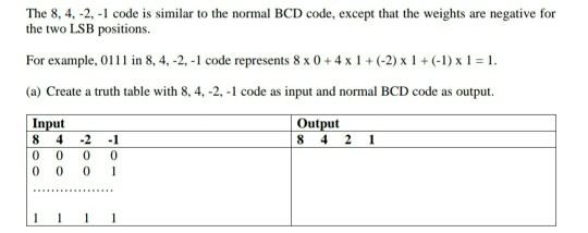
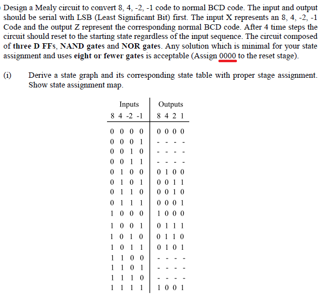
Design a Mealy circuit to convert 8, 4, -2, -1 code to normal BCD code. The input and output should be serial with LSB (Least Significant Bit) first. The input X represents an 8, 4, -2, -1 Code and the output Z represent the corresponding normal BCD code. After 4 time steps the circuit should reset to the starting state regardless of the input sequence. The circuit composed of three D FFs, NAND gates and NOR gates. Any solution which is minimal for your state assignment and uses eight or fewer gates is acceptable (Assign 0000 to the reset stage). (1) Derive a state graph and its corresponding state table with proper stage assignment. Show state assignment map. Inputs 84 -2 -1 Outputs 8 4 2 1 0 0 0 0 0 0 0 0 0 0 0 1 0 0 1 0 0 0 1 1 0 1 0 0 0 1 0 1 0 1 1 0 0 1 1 1 1 0 0 0 1001 1 0 1 0 1011 1 1 0 0 1 1 0 1 1 1 1 0 0100 0011 0010 0001 1000 0111 0110 0101 1001 The 8, 4, -2, -1 code is similar to the normal BCD code, except that the weights are negative for the two LSB positions For example, 0111 in 8, 4,-2 -1 code represents 8 x 0 +4 x 1 + (-2) x 1 + (-1) x1 = 1. (a) Create a truth table with 8, 4, -2, -1 code as input and normal BCD code as output. Input 8 4 -2 -1 0 0 0 0 0 0 0 Output 8 4 2 1 - - 1 1 Design a Mealy circuit to convert 8, 4, -2, -1 code to normal BCD code. The input and output should be serial with LSB (Least Significant Bit) first. The input X represents an 8, 4, -2, -1 Code and the output Z represent the corresponding normal BCD code. After 4 time steps the circuit should reset to the starting state regardless of the input sequence. The circuit composed of three D FFs, NAND gates and NOR gates. Any solution which is minimal for your state assignment and uses eight or fewer gates is acceptable (Assign 0000 to the reset stage). (1) Derive a state graph and its corresponding state table with proper stage assignment. Show state assignment map. Inputs 84 -2 -1 Outputs 8 4 2 1 0 0 0 0 0 0 0 0 0 0 0 1 0 0 1 0 0 0 1 1 0 1 0 0 0 1 0 1 0 1 1 0 0 1 1 1 1 0 0 0 1001 1 0 1 0 1011 1 1 0 0 1 1 0 1 1 1 1 0 0100 0011 0010 0001 1000 0111 0110 0101 1001 The 8, 4, -2, -1 code is similar to the normal BCD code, except that the weights are negative for the two LSB positions For example, 0111 in 8, 4,-2 -1 code represents 8 x 0 +4 x 1 + (-2) x 1 + (-1) x1 = 1. (a) Create a truth table with 8, 4, -2, -1 code as input and normal BCD code as output. Input 8 4 -2 -1 0 0 0 0 0 0 0 Output 8 4 2 1 - - 1 1
Step by Step Solution
There are 3 Steps involved in it
Step: 1

Get Instant Access to Expert-Tailored Solutions
See step-by-step solutions with expert insights and AI powered tools for academic success
Step: 2

Step: 3
Ace Your Homework with AI
Get the answers you need in no time with our AI-driven, step-by-step assistance
Get Started
Audit Skill Management Ref PPAP ISO 9000 And ISO 14000 Series
Authors: FULBODH CHAUDHARY
1st Edition
1520470843, 978-1520470849