Note: use DH model and matlab to solve
Answer: Denavit-Hartenberg model of an arm or leg (geometric model) with standard movements for rehabilitation (real parameter: dimensions and limits of movement)
Code in Matlab
Please check the part "Results to deliver"


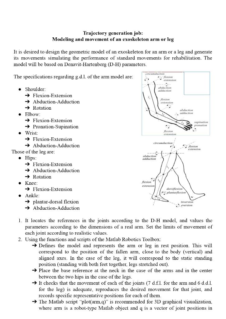
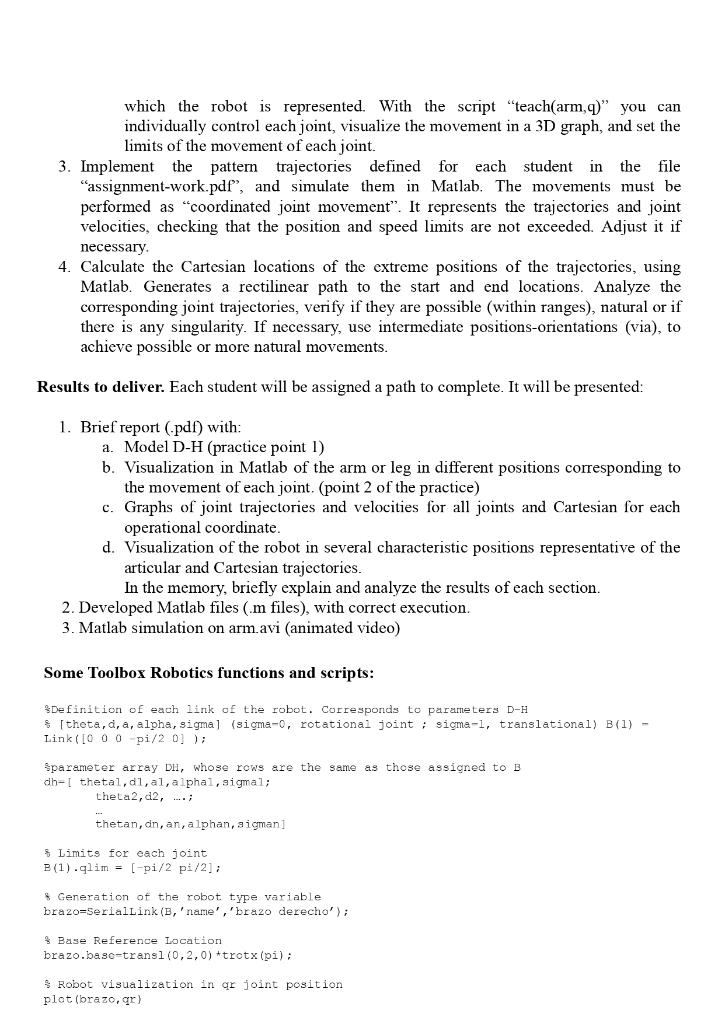
Trajectory generation job: Modeling and movement of an exoskeleton arm or leg It is desired to design the geometric model of an exoskeleton for an arm or a leg and generate its movements simulating the performance of standard movements for rehabilitation. The model will be based on Denavit-Hartenberg (D-H) parameters. The specifications regarding g.d.l. of the arm model are: Circa flexion tension abduction aduction flexion extension aduction eduction supination Next extensic circumduction Shoulder: Flexion-Extension Abduction-Adduction Rotation Elbow: Flexion-Extension Pronation-Supination Wrist: Flexion-Extension Abduction-Adduction Those of the leg are: Hips: Flexion-Extension Abduction-Adduction Rotation Knee: Flexion-Extension Ankle: plantar-dorsal flexion Abduction-Adduction Rexion extension abduction adduction flexion extension dorsiflexion 3 planlarflexion version version 1. It locates the references in the joints according to the D-H model, and values the parameters according to the dimensions of a real arm. Set the limits of movement of each joint according to realistic values. 2. Using the functions and scripts of the Matlab Robotics Toolbox: Defines the model and represents the arm or leg in rest position. This will correspond to the position of the fallen arm, close to the body (vertical) and aligned axes. In the case of the leg, it will correspond to the static standing position (standing with both feet together, legs stretched out). Place the base reference at the neck in the case of the arms and in the center between the two hips in the case of the legs. It checks that the movement of each of the joints (7 d.f.l. for the arm and 6 d.d.l. for the leg) is adequate, reproduces the desired movement for that joint, and records specific representative positions for each of them. The Matlab script "plot(arm,q)" is recommended for 3D graphical visualization, where arm is a robot-type Matlab object and q is a vector of joint positions in which the robot is represented. With the script "teach(arm,q)" you can individually control each joint, visualize the movement in a 3D graph, and set the limits of the movement of each joint. 3. Implement the pattern trajectories defined for each student in the file "assignment-work.pdf", and simulate them in Matlab. The movements must be performed as "coordinated joint movement". It represents the trajectories and joint velocities, checking that the position and speed limits are not exceeded. Adjust it if necessary 4. Calculate the Cartesian locations of the extreme positions of the trajectories, using Matlab. Generates a rectilinear path to the start and end locations. Analyze the corresponding joint trajectories, verify if they are possible (within ranges), natural or if there is any singularity. If necessary, use intermediate positions-orientations (via), to achieve possible or more natural movements. Results to deliver. Each student will be assigned a path to complete. It will be presented: 1. Brief report (pdf) with: a. Model D-H (practice point I) b. Visualization in Matlab of the arm or leg in different positions corresponding to the movement of each joint. (point 2 of the practice) c. Graphs of joint trajectories and velocities for all joints and Cartesian for each operational coordinate. d. Visualization of the robot in several characteristic positions representative of the articular and Cartesian trajectories. In the memory, briefly explain and analyze the results of each section. 2. Developed Matlab files (.m files), with correct execution. 3. Matlab simulation on arm.avi (animated video) Some Toolbox Robotics functions and scripts: Definition of each link of the robot. Corresponds to parameters D-H $(theta, a, a, alpha, signal (sigma-o, rotational joint ; sima-1, translational) B(1) - Link(IO O O pi/20]); Sparameter array DH, whose rows are the same as those assigned to B dh-[ thetal, di, al, alphal, sigmal; theta2,02, thetan, on, an, alphan, aigman Limits for each joint B(1).qlim = [-pi/2 pi/21; Generation of the robot type variable brazo=SerialLink (B,'name','brazo derecho'); $ Base Reference Location brazo.base-transl(0,2,0) *trotx (pi): Robot visualization in or joint position plot (brazo,ar) * robot visualization and manual joint control from or initial joint position teach (brazo, 90) * articular trajectory from qi to of, calculating 100 intermediate positions trayart-jtraj (qi,qf, 100); calculates the same but using the length of the time vector t (to set speed) trayart-jtraj (qi,qf, t); linear cartesian path from To to Tf, calculating 100 intermediate positions trayear=ctraj (Ti,Tf, 100); * computea the same but using the length of the time vector t traycar=ctraj (Ti,TE,t); % Calculation of Cartesian location T from the parameters dh of the robot in joint position 9 (Direct goometric model) T-kine (brazo,q) Calculation of the joint position a from the parameters dh of the robot in Cartesian location T (Inverse geometric model). 90 is the initial value (by default qo=0). q-ikine (brazo, T, 90) More features and demos on Toolbox Robotics in moodle 2


