Question
NOTE: YOU NEED GNS3 SOFTWARE TO DO THIS QUESTION Step 1 IP addressing of MPLS Core and OSPF First bring 3 routers into your topology
NOTE: YOU NEED GNS3 SOFTWARE TO DO THIS QUESTION
Step 1 IP addressing of MPLS Core and OSPF
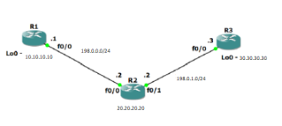
First bring 3 routers into your topology R1, R2, R3 position them as below. Then address the routers and configure ospf to ensure loopback connectivity between R1 and R3
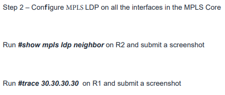
Step 3- MPLS BGP configuration between R1 and R3
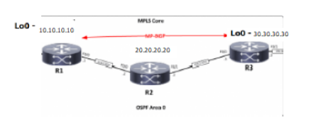
You need to establish a Multi Protocol BGP session between R1 and R3 by configuring the vpnv4 address family
run #show bgp vpnv4 unicast all summary on R1 and submit a screenshot
step 4- Add two more routers, create VRFs
You will need to add two more routers into the topology as per below image
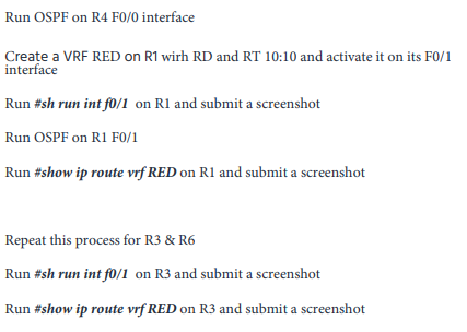
configure R1, R4, R3, and R6 interfaces accordingly
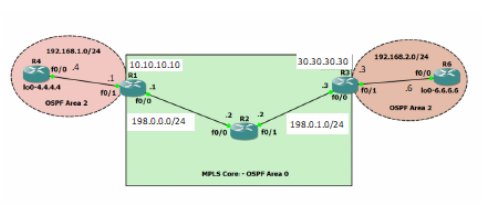
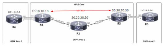
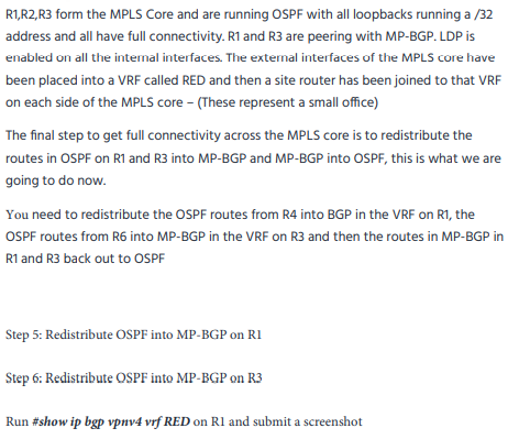
R1 10/0 fo/o LOO 10.10.2016 198.00024 LO 30.30.30.30 - 18.0.1024 R2 10/0 T/OU 20.20.20.20 Step 2 - Configure MPLS LDP on all the interfaces in the MPLS Core Run #show mpls ldp neighbor on R2 and submit a screenshot Run #trace 30.30.30.30 on R1 and submit a screenshot MPS Come Loo - 10.10.10.10 LOO - 30.30.30.30 PSGP 20.20.20.20 R3 RI R2 OSTA 192.168.1.0/24 30.30.30.30 10.10.10.10 10/04 192.168.2.0/24 RS 10/0 SX 10/1 OSPF Area 2 100-4444 OSPF Area 2 10/1 60-66.66 fo/ 198.0.0.0/24 198.0.1.0/24 fo/ MPL Core- OSPF Area Run OSPF on R4 F0/0 interface Create a VRF RED on R1 with RD and RT 10:10 and activate it on its F0/1 interface Run #sh run int fo/1 on R1 and submit a screenshot Run OSPF on R1 F0/1 Run #show ip route vrf RED on R1 and submit a screenshot Repeat this process for R3 & R6 Run #sh run int fo/1 on R3 and submit a screenshot Run #show ip route vrf RED on R3 and submit a screenshot MPLS Core 10.10.10.10 L-4444 MP-BOP 30.30.30.30 LO-6666 20.20.20.20 RI R3 R6 R4 R2 OSPF Area OSPF Area 2 OSPF Area 2 R1,R2,R3 form the MPLS Core and are running OSPF with all loopbacks running a /32 address and all have full connectivity. R1 and R3 are peering with MP-BGP. LDP is enabled on all the internal interfaces. The external interfaces of the MPLS core have been placed into a VRF called RED and then a site router has been joined to that VRF on each side of the MPLS core - (These represent a small office) The final step to get full connectivity across the MPLS core is to redistribute the routes in OSPF on R1 and R3 into MP-BGP and MP-BGP into OSPF, this is what we are going to do now You need to redistribute the OSPF routes from R4 into BGP in the VRF on R1, the OSPF routes from R6 into MP-BGP in the VRF on R3 and then the routes in MP-BGP in R1 and R3 back out to OSPF Step 5: Redistribute OSPF into MP-BGP on RI Step 6: Redistribute OSPF into MP-BGP on R3 Run #show ip bgp vpnv4 vrf RED on Rl and submit a screenshot Run #show ip bgp Vprve vrf RED on R3 and submit a screenshot Step 7: Redistribute BGP into OSPF into on Ri Step 8 : Redistribute BGP into OSPF on R3 Run #ping 6.6.6.6 on R4 and submit a screenshot Run #ping 4.4.4.4 on R6 and submit a screenshot Save and submit your GNS3 final file
Step by Step Solution
There are 3 Steps involved in it
Step: 1

Get Instant Access to Expert-Tailored Solutions
See step-by-step solutions with expert insights and AI powered tools for academic success
Step: 2

Step: 3
Ace Your Homework with AI
Get the answers you need in no time with our AI-driven, step-by-step assistance
Get Started