

Answered step by step
Verified Expert Solution
Question
1 Approved Answer
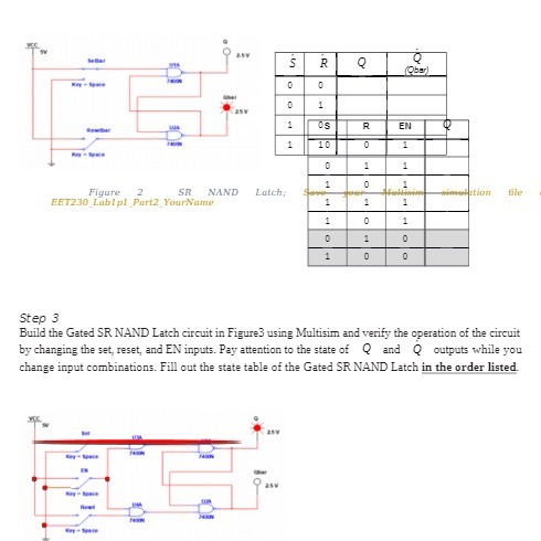
O R Q Q 1 R EN 10 0 1 1 1 file Figure 2 SR NAND Latch, 1 EET230 Labl pl Part2 YourName 1
Step by Step Solution
There are 3 Steps involved in it
Step: 1

Get Instant Access to Expert-Tailored Solutions
See step-by-step solutions with expert insights and AI powered tools for academic success
Step: 2

Step: 3
Ace Your Homework with AI
Get the answers you need in no time with our AI-driven, step-by-step assistance
Get Started
University Physics with Modern Physics
Authors: Hugh D. Young, Roger A. Freedman, Lewis Ford
12th Edition
978-0321501479, 9780805321876, 321501470, 978-0321501219