

Answered step by step
Verified Expert Solution
Question
1 Approved Answer
Objective: To demonstrate the operation and characteristics of NAND and NOR gates. Device List: 44. Connect the circuit as shown in Fig. 1.4 and record
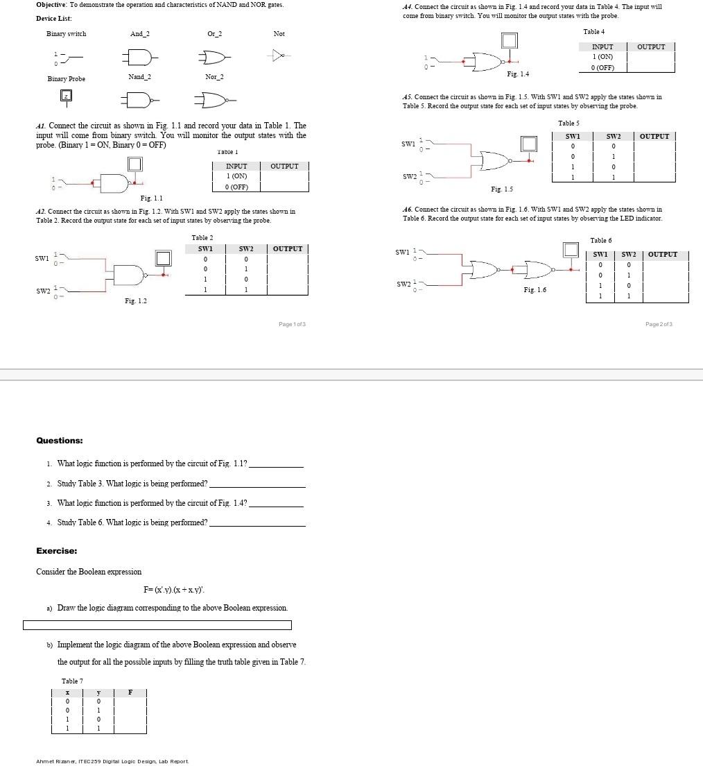
Objective: To demonstrate the operation and characteristics of NAND and NOR gates. Device List: 44. Connect the circuit as shown in Fig. 1.4 and record your data in Table 4. The input will come from binary switch You will monitor the output states with the probe Binary switch And_2 Or_2 Not Table 4 OUTPUT INPUT 1 (ON) O (OFF) Nand 2 Binary Probe Nor_2 Fig. 1.4 1 45. Connect the circuit as shown in Fig. 1.5. With SWT and SW2 apply the states shown in Table 5. Record the output state for each set of input states by observing the probe. 41. Connect the circuit as shown in Fig. 1.1 and record your data in Table 1. The input will come from binary switch You will monitor the output states with the probe. (Binary 1-ON Binary 0 = OFF) Table 1 SW2 OUTPUT SW 0- Table 5 SW1 0 0 1 1 0 1 1 0 0 1 1 SW2 Fig. 1.5 INPUT OUTPUT 1 (ON) O (OFF) Fig. 1.1 42. Connect the circuit as shown in Fig. 1.2. With SW1 and SW2 apply the states shown in Table 2. Record the output state for each set of input states by observing the probe. 46. Connect the circuit as shown in Fig. 1.6. With SW1 and SW2 apply the states shown in Table 6. Record the output state for each set of input states by observing the LED indicator Table 6 OUTPUT swi 1 OUTPUT SWI Table 2 SW1 0 0 1 1 1 SW2 0 1 0 1 SW1 SW2 0 0 0 1 0 1 1 1 SW22 SW2 Fig. 1.6 0 Fig. 1.2 Page 1 of 3 Page 2 of 3 Questions: 1. What logic function is performed by the circuit of Fig. 1.1? 2. Study Table 3. What logic is being performed? 3. What logic fimction is performed by the circuit of Fig. 1.4? 4. Study Table 6. What logic is being performed? Exercise: Consider the Boolean expression F=(x'.y) (x + xy) a) Draw the logic diagram corresponding to the above Boolean expression. b) Implement the logic diagram of the above Boolean expression and observe the output for all the possible inputs by filling the truth table given in Table 7. Table 7 F 1 0 0 1 1 y 0 1 0 1 Ahmet Rizaner, ITEC 259 Digital Logic Design Lab Report
Step by Step Solution
There are 3 Steps involved in it
Step: 1

Get Instant Access to Expert-Tailored Solutions
See step-by-step solutions with expert insights and AI powered tools for academic success
Step: 2

Step: 3
Ace Your Homework with AI
Get the answers you need in no time with our AI-driven, step-by-step assistance
Get Started
The Temple Of Django Database Performance
Authors: Andrew Brookins
1st Edition
1734303700, 978-1734303704