Answered step by step
Verified Expert Solution
Link Copied!

Question

1 Approved Answer

OBJECTIVES 1. To investigate and analyze the operation of JK flip-flop. 2. To design a synchronous counter using JK flip-flops. SOFTWARE CEDAR Logic Simulator INTRODUCTION
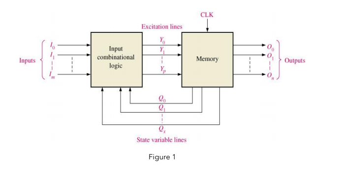
image text in transcribed

image text in transcribed

image text in transcribed

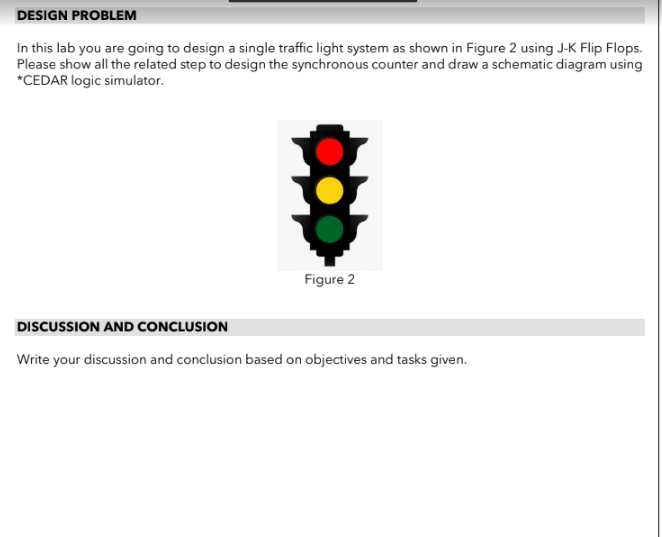
OBJECTIVES 1. To investigate and analyze the operation of JK flip-flop. 2. To design a synchronous counter using JK flip-flops. SOFTWARE CEDAR Logic Simulator INTRODUCTION A counter is a digital sequential logic device that will go through a certain predefined state based on the application of the input pulses. There are two main types of counters: Asynchronous Counter and Synchronous Counter. The counter utilizes flip-flop to store binary information, where the number of flip- flops used will determine the capability of counting bits. Figure 1 shows the general clocked sequential circuit CLK Excitation lines Y Inputs Input combinational logic Memory Outputs . State variable lines Figure 1 DESIGN PROBLEM In this lab you are going to design a single traffic light system as shown in Figure 2 using J-K Flip Flops. Please show all the related step to design the synchronous counter and draw a schematic diagram using *CEDAR logic simulator. Figure 2 DISCUSSION AND CONCLUSION Write your discussion and conclusion based on objectives and tasks given. OBJECTIVES 1. To investigate and analyze the operation of JK flip-flop. 2. To design a synchronous counter using JK flip-flops. SOFTWARE CEDAR Logic Simulator INTRODUCTION A counter is a digital sequential logic device that will go through a certain predefined state based on the application of the input pulses. There are two main types of counters: Asynchronous Counter and Synchronous Counter. The counter utilizes flip-flop to store binary information, where the number of flip- flops used will determine the capability of counting bits. Figure 1 shows the general clocked sequential circuit CLK Excitation lines Y Inputs Input combinational logic Memory Outputs . State variable lines Figure 1 DESIGN PROBLEM In this lab you are going to design a single traffic light system as shown in Figure 2 using J-K Flip Flops. Please show all the related step to design the synchronous counter and draw a schematic diagram using *CEDAR logic simulator. Figure 2 DISCUSSION AND CONCLUSION Write your discussion and conclusion based on objectives and tasks given
Step by Step Solution

There are 3 Steps involved in it

Step: 1

blur-text-image

Get Instant Access to Expert-Tailored Solutions

See step-by-step solutions with expert insights and AI powered tools for academic success

Step: 2

blur-text-image

Step: 3

blur-text-image

Ace Your Homework with AI

Get the answers you need in no time with our AI-driven, step-by-step assistance

Get Started

Recommended Textbook for

Linked Data A Geographic Perspective

Authors: Glen Hart, Catherine Dolbear

1st Edition

1000218910, 9781000218916

More Books

Students also viewed these Databases questions

Question

What is the most important part of any HCM Project Map and why?

Answered: 1 week ago