Objectives: List the objectives of the experiment.
Equipment: List the equipment and components that you used.
Procedure:
- Write the steps you have done during your experiment.
- Use passive voice.
- Include any circuit, table, figure required.
- Simulate the circuits and include the results in your report in any format you prefer.
Questions:
Answer each question (if any) included in lab sheet
Conclusion:
Write down about the following:
- what was this experiment about and whether you achieved the objectives.
- conclusions you can draw.
- difficulties you faced.
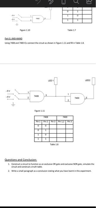
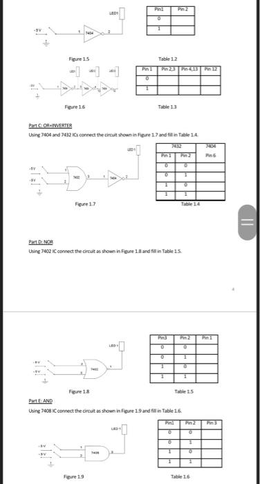
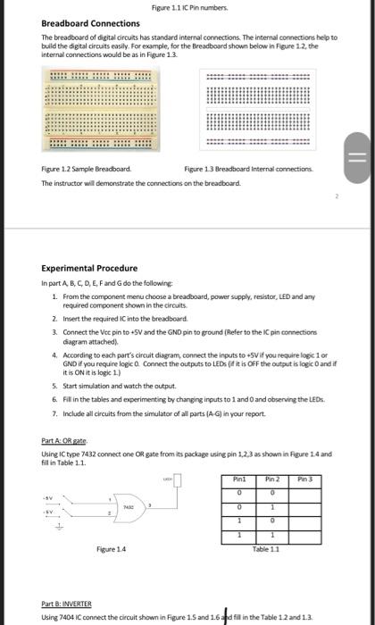
0 1 1 Figure 1.10 Table 1 Part GAND.NAND Using 7408 and 7400 is connect the circuts shown in Figure 1.11 and fill in Table 13 LED 1 LED -5V .5V 7408 Figure 111 n1 in 0 0 0 1 0 1 Table 18 Questions and Conclusion: 1. Construct a circult to function as an exclusive Okute and exclusive Norge, simdiate the circuit and construct a truth table 2 Write a small paragraph as a conclusion stating what you have learnt in this experiment Pin Pn2 LED 11 Figure 1.5 Table 12 Pn3 0 Figure 16 Table 13 Part CORINVERTER Using 700 and 7632 is connect the circuit shown in Figure 17 and fill in Tale 14 Hin 0 SY la 1 1 Feue 1.7 PartDNOR Using 7402 Connect the circuit as shown in Figure 18 and fit in Table 15 O Figure 18 Part E. AND Using 7408C connect the cult as shown in pure 19 and fill in Table 1.6 Pne Pn2 0 1 1 Figure 19 Table 16 Figure 1.11 Pin numbers Breadboard Connections The breadboard of digital circuits has standard internal connections. The internal connections help to build the digital circuits easily. For example, for the Breadboard shown below in Figure 12, the Internal connections would be as in Figure 13 Figure 1.2 Sample Breadboard Figure 1.3 Breadboard Internal connections The instructor wil demonstrate the connections on the breadboard. Experimental Procedure In part A, B, C, D, E, F and G do the following 1. From the component menu choose a breadboard, power supply, resistor, LED and any required component shown in the circuits 2. Insert the required IC into the breadboard. 3. Connect the Vec pin to +5V and the GND pinto ground (Refer to the IC pin connections diagram attached) 4. According to each part's circuit diagram, connect the inputs to +5V if you require log1 or GND if you require logico Connect the outputs to LEDs (if it is OFF the output is logic and if it is ON it is log 1.) 5. Start simulation and watch the output 6. Fill in the tables and experimenting by changing inputs to 1 and 0 and observing the LEDx. 7. Include all circuits from the simulator of all parts (AG) in your report Part A OR pate Using IC type 7432 connect one OR gate from its package using pin 1.2.3 as shown in Figure 14 and fill in Table 11. Pin3 0 0 Me 0 1 1 0 1 1 Figure 1.4 Table 11 Part B: INVERTER Using 7404 IC connect the circuit shown in Figure 1.5 and 1.6d fill in the Table 12 and 13. 4:40 Prepared by Dr. Hesse und Objective: To study the basic logic functions of the AND OIL INVESTER NAD NO representations, truth tales, le diagrams and Boolean it Introduction: The inputs and output of dal circuits et aste voltage to provide.com and standard basis for comparison, the two voltage levels apresented by y Sor more voltage speed by the rest represented by Vol . Abascute operation represented in the following AND a multi-input circuit in which the output nationalitet OR a multi imparcult in which the autput is al when you al INVERTER the output is when the input and the whether NAND AND flowed by INVERTER NOR OR fotowed by INVERTER Simulator: To perform the procedure of testing the functions of the topeste doudbud med tilberimentThe simulator is Thiers Sign up and subscribe. Your instructor will provide you with a demonstration of the simu Equipment Required: One K 70 liter One Type de De Type 70 od 2 NANDE One Type 7432 Quad 2 ORE One Twoude Note LEDs, Restors (220 cm. Power Supply IC Pin Connections linggates are available in integrated Circus B. Each of these in this experientia The beim progress in condiciones we way from the pins, as shown in Figure 11 below. Pinis represented by a dingle or you identify the location of pin 1 by the Indes notch at the end of the case where and Figures in murers Breadboard Connections The breadboard of lots has standard internal corection. The roma corectory build the digital cruty Role for the readboard shown belowe 12. the Welconnections would be as in Figure 13 0 1 1 Figure 1.10 Table 1 Part GAND.NAND Using 7408 and 7400 is connect the circuts shown in Figure 1.11 and fill in Table 13 LED 1 LED -5V .5V 7408 Figure 111 n1 in 0 0 0 1 0 1 Table 18 Questions and Conclusion: 1. Construct a circult to function as an exclusive Okute and exclusive Norge, simdiate the circuit and construct a truth table 2 Write a small paragraph as a conclusion stating what you have learnt in this experiment Pin Pn2 LED 11 Figure 1.5 Table 12 Pn3 0 Figure 16 Table 13 Part CORINVERTER Using 700 and 7632 is connect the circuit shown in Figure 17 and fill in Tale 14 Hin 0 SY la 1 1 Feue 1.7 PartDNOR Using 7402 Connect the circuit as shown in Figure 18 and fit in Table 15 O Figure 18 Part E. AND Using 7408C connect the cult as shown in pure 19 and fill in Table 1.6 Pne Pn2 0 1 1 Figure 19 Table 16 Figure 1.11 Pin numbers Breadboard Connections The breadboard of digital circuits has standard internal connections. The internal connections help to build the digital circuits easily. For example, for the Breadboard shown below in Figure 12, the Internal connections would be as in Figure 13 Figure 1.2 Sample Breadboard Figure 1.3 Breadboard Internal connections The instructor wil demonstrate the connections on the breadboard. Experimental Procedure In part A, B, C, D, E, F and G do the following 1. From the component menu choose a breadboard, power supply, resistor, LED and any required component shown in the circuits 2. Insert the required IC into the breadboard. 3. Connect the Vec pin to +5V and the GND pinto ground (Refer to the IC pin connections diagram attached) 4. According to each part's circuit diagram, connect the inputs to +5V if you require log1 or GND if you require logico Connect the outputs to LEDs (if it is OFF the output is logic and if it is ON it is log 1.) 5. Start simulation and watch the output 6. Fill in the tables and experimenting by changing inputs to 1 and 0 and observing the LEDx. 7. Include all circuits from the simulator of all parts (AG) in your report Part A OR pate Using IC type 7432 connect one OR gate from its package using pin 1.2.3 as shown in Figure 14 and fill in Table 11. Pin3 0 0 Me 0 1 1 0 1 1 Figure 1.4 Table 11 Part B: INVERTER Using 7404 IC connect the circuit shown in Figure 1.5 and 1.6d fill in the Table 12 and 13. 4:40 Prepared by Dr. Hesse und Objective: To study the basic logic functions of the AND OIL INVESTER NAD NO representations, truth tales, le diagrams and Boolean it Introduction: The inputs and output of dal circuits et aste voltage to provide.com and standard basis for comparison, the two voltage levels apresented by y Sor more voltage speed by the rest represented by Vol . Abascute operation represented in the following AND a multi-input circuit in which the output nationalitet OR a multi imparcult in which the autput is al when you al INVERTER the output is when the input and the whether NAND AND flowed by INVERTER NOR OR fotowed by INVERTER Simulator: To perform the procedure of testing the functions of the topeste doudbud med tilberimentThe simulator is Thiers Sign up and subscribe. Your instructor will provide you with a demonstration of the simu Equipment Required: One K 70 liter One Type de De Type 70 od 2 NANDE One Type 7432 Quad 2 ORE One Twoude Note LEDs, Restors (220 cm. Power Supply IC Pin Connections linggates are available in integrated Circus B. Each of these in this experientia The beim progress in condiciones we way from the pins, as shown in Figure 11 below. Pinis represented by a dingle or you identify the location of pin 1 by the Indes notch at the end of the case where and Figures in murers Breadboard Connections The breadboard of lots has standard internal corection. The roma corectory build the digital cruty Role for the readboard shown belowe 12. the Welconnections would be as in Figure 13