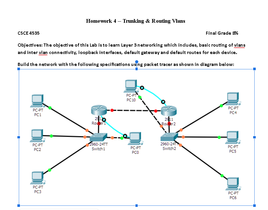
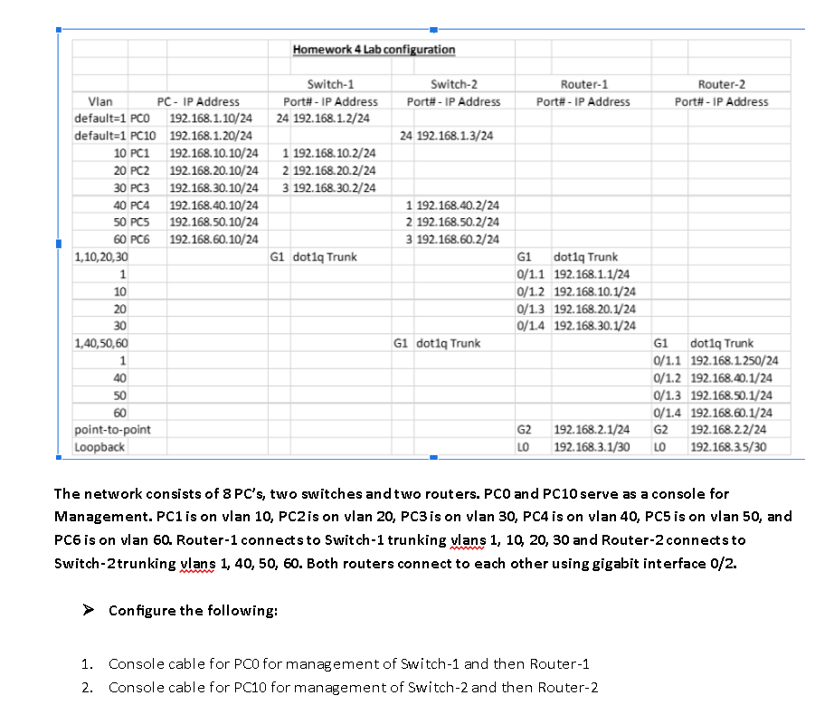
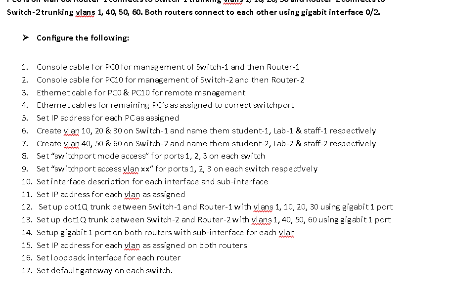
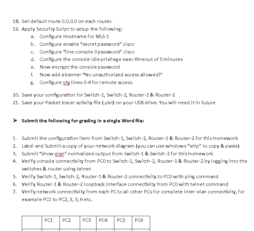
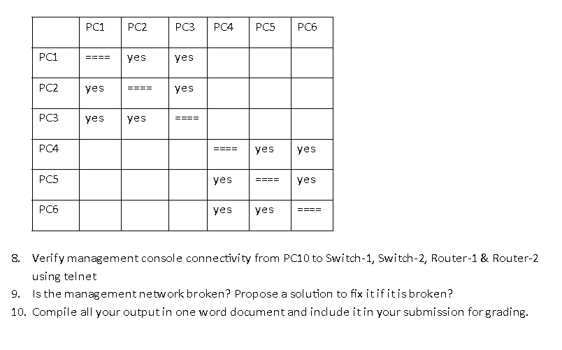
Objectives: The objective of this Lab is to learn Laver 3 networking which includes, basic routing of vlans and inter vlan connectivity, loopback int erfaces, default gateway and default routes for each device. The network consists of 8PC 's, two switches and two routers. PCO and PC10 serve as a console for Management. PC1 is on vlan 10, PC2 is on vlan 20, PC3 is on vlan 30,PC4 is on vlan 40,PC5 is on vlan 50 , and PC6 is on vlan 60 . Router- 1 connects to Switch-1 trunking vlans 1,10,20,30 and Router-2 connects to Switch-2trunking ylans 1,40,50,60. Both routers connect to each other using gigabit interface 0/2. Configure the following: 1. Console cable for PCO for management of Switch-1 and then Router-1 2. Console cable for PC10 for management of Switch-2 and then Router-2 Switch-2trunking ylans 1,40,50,60. Both routers connect to each other using gigabit int erface 0/2. Configure the following: 1. Console cable for PCo for management of Switch-1 and then Router-1 2. Console cable for PC10 for management of Switch-2 and then Router-2 3. Ethernet cable for PCO&PC10 for remote management 4. Ethernet cables for remaining PC s as assigned to correct switchport 5. Set IP address for each PC as assigned 6. Create vlan 10,20&30 on Switch-1 and name them student-1, Lab-1 \& staff-1 respectively 7. Create ylan 40, 50 \& 60 on Switch-2 and name them student-2, Lab-2 \& staff-2 respectively 8. Set "switchport mode access" for ports 1, 2, 3 on each switch 9. Set "switchport access y lan xx for ports 1, 2, 3 on each switch respectively 10. Setinterface description for each interface and sub-interface 11. Set IP address for each van as assigned 12. Set up dot1Q trunk between Switch-1 and Router-1 with wlans 1, 10, 20, 30 using gigabit 1 port 13. Set up dot1Q trunk between Switch-2 and Router-2 with ylans 1, 40, 50, 60 using gigabit 1 port 14. Setup gigabit 1 port on both routers with sub-interface for each ylan 15. Set IP address for each y lan as assigned on both routers 16. Setloopback interface for each router 17. Set defaultgateway on each switch. 18. Set default route 0.0 .0 .0 on each router. 19. Apply Security Script to setup the following: a. Configure Hostname for MLS-1 b. Configure enable "secret password" cisco c. Configure "line console 0 password" cisco d. Configure the console Idle privilege exec timeout of 5 minutes e. Now encrypt the console password f. Now add abanner "No unauthorized access allowed!" g. Configure yty lines 04 for remote access 20. Save your configuration for Switch-1, switch-2, Router-1 \& Router-2 21. Save your Packet tracer activity file (.pkt) on your USB drive. You will need it in future Submit the following for grading in a single Word file: 1. Submit the configuration item from Switch-1, Switch-2, Router-1 \& Router-2 for this homework 2. Label and Submit a copy of your network diagram (you can use windows "snip" to copy \& paste) 3. Submit "show Wlan" normalized output from Switch-1 \& Switch-2 for thishomework 4. Verify console connectivity from PCo to Switch-1, Switch-2, Router-1 \& Router-2 by logging into the switches \& router using telnet 5. Verify Switch-1, Switch-2, Router-1 \& Router-2 connectivity to PCo with ping command 6. Verify Router-1 \& Router-2 loopback interface connectivity from PCo with telnet command 7. Verify network connectivity from each PC to all other PCs for complete inter-vlan connectivity, for example PC1 to PCC2,3,5,6 etc. 8. Verify management console connectivity from PC10 to Switch-1, Switch-2, Router-1 \& Router-2 using telnet 9. Is the management network broken? Propose a solution to fix it if it is broken? 10. Compile all your output in one word document and include it in your submission forgrading. Please note that the grading for Homeworks and Labs requires that you configure the correct vlans on the switch and trunk based on the design. Configuring access Vlans or configuring all vlans on trunk is not acceptable. I have seen many networks destroyed by this bad practice. I want to make sure that you do not leam this bad habit. You will not get full credit for work if you use this bad practice for homeworks and Labs