Answered step by step
Verified Expert Solution
Question
1 Approved Answer
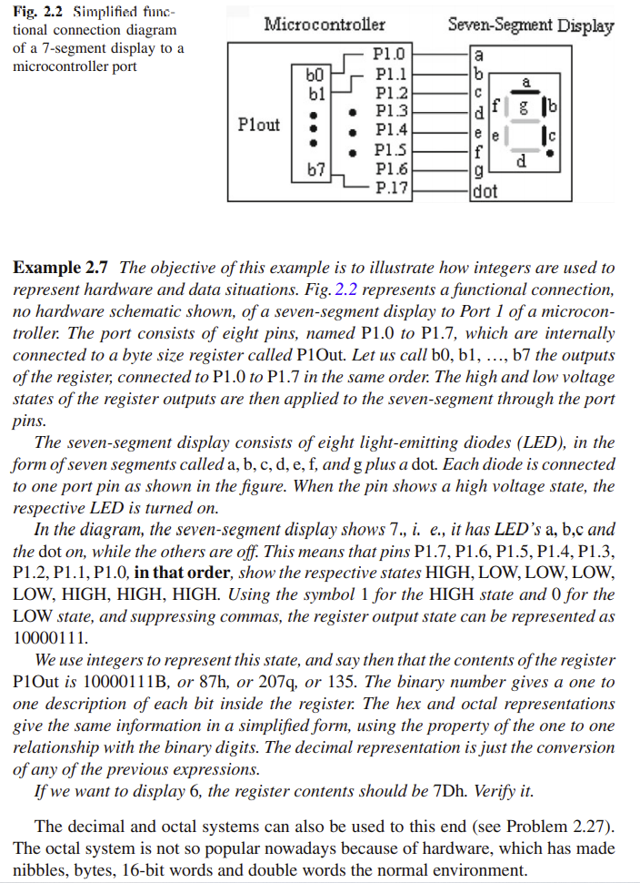
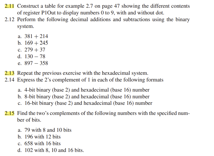
Only 2.11, 2.13, 2.15. Microcontroller Seven-Segment Display Fig. 2.2 Simplified func- tional connection diagram of a 7-segment display to a microcontroller port b0 b1 a


Only 2.11, 2.13, 2.15.
Microcontroller Seven-Segment Display Fig. 2.2 Simplified func- tional connection diagram of a 7-segment display to a microcontroller port b0 b1 a g 16 . Plout : P1.0 P1.1 P1.2 P1.3 P1.4 P1.5 P1.6 P.17 a b c d f e le f g dot d 67 Example 2.7 The objective of this example is to illustrate how integers are used to represent hardware and data situations. Fig. 2.2 represents a functional connection, no hardware schematic shown, of a seven-segment display to Port 1 of a microcon- troller. The port consists of eight pins, named P1.0 to P1.7, which are internally connected to a byte size register called P10ut. Let us call bo, bl, ..., b7 the outputs of the register, connected to P1.0 to P1.7 in the same order. The high and low voltage states of the register outputs are then applied to the seven-segment through the port pins. The seven-segment display consists of eight light-emitting diodes (LED), in the form of seven segments called a, b, c, d, e, f, and g plus a dot. Each diode is connected to one port pin as shown in the figure. When the pin shows a high voltage state, the respective LED is turned on. In the diagram, the seven-segment display shows 7., i. e., it has LED's a, b,c and the dot on, while the others are off. This means that pins P1.7, P1.6, P1.5, P1.4, P1.3, P1.2, P1.1, P1.0, in that order, show the respective states HIGH, LOW, LOW, LOW, LOW, HIGH, HIGH, HIGH. Using the symbol 1 for the HIGH state and 0 for the LOW state, and suppressing commas, the register output state can be represented as 10000111. We use integers to represent this state, and say then that the contents of the register P1Out is 10000111B, or 87h, or 207q, or 135. The binary number gives a one to one description of each bit inside the register. The hex and octal representations give the same information in a simplified form, using the property of the one to one relationship with the binary digits. The decimal representation is just the conversion of any of the previous expressions. If we want to display 6, the register contents should be 7Dh. Verify it. The decimal and octal systems can also be used to this end (see Problem 2.27). The octal system is not so popular nowadays because of hardware, which has made nibbles, bytes, 16-bit words and double words the normal environment. 2.11 Construct a table for example 2.7 on page 47 showing the different contents of register P1Out to display numbers 0 to 9, with and without dot. 2.12 Perform the following decimal additions and subtractions using the binary system. a. 381 + 214 b. 169 + 245 c. 279 + 37 d. 130 78 e. 897 358 2.13 Repeat the previous exercise with the hexadecimal system. 2.14 Express the 2s complement of 1 in each of the following formats a. 4-bit binary (base 2) and hexadecimal (base 16) number b. 8-bit binary (base 2) and hexadecimal (base 16) number c. 16-bit binary (base 2) and hexadecimal (base 16) number 2.15 Find the twos complements of the following numbers with the specified num- ber of bits. a. 79 with 8 and 10 bits b. 196 with 12 bits c. 658 with 16 bits d. 102 with 8, 10 and 16 bits. Microcontroller Seven-Segment Display Fig. 2.2 Simplified func- tional connection diagram of a 7-segment display to a microcontroller port b0 b1 a g 16 . Plout : P1.0 P1.1 P1.2 P1.3 P1.4 P1.5 P1.6 P.17 a b c d f e le f g dot d 67 Example 2.7 The objective of this example is to illustrate how integers are used to represent hardware and data situations. Fig. 2.2 represents a functional connection, no hardware schematic shown, of a seven-segment display to Port 1 of a microcon- troller. The port consists of eight pins, named P1.0 to P1.7, which are internally connected to a byte size register called P10ut. Let us call bo, bl, ..., b7 the outputs of the register, connected to P1.0 to P1.7 in the same order. The high and low voltage states of the register outputs are then applied to the seven-segment through the port pins. The seven-segment display consists of eight light-emitting diodes (LED), in the form of seven segments called a, b, c, d, e, f, and g plus a dot. Each diode is connected to one port pin as shown in the figure. When the pin shows a high voltage state, the respective LED is turned on. In the diagram, the seven-segment display shows 7., i. e., it has LED's a, b,c and the dot on, while the others are off. This means that pins P1.7, P1.6, P1.5, P1.4, P1.3, P1.2, P1.1, P1.0, in that order, show the respective states HIGH, LOW, LOW, LOW, LOW, HIGH, HIGH, HIGH. Using the symbol 1 for the HIGH state and 0 for the LOW state, and suppressing commas, the register output state can be represented as 10000111. We use integers to represent this state, and say then that the contents of the register P1Out is 10000111B, or 87h, or 207q, or 135. The binary number gives a one to one description of each bit inside the register. The hex and octal representations give the same information in a simplified form, using the property of the one to one relationship with the binary digits. The decimal representation is just the conversion of any of the previous expressions. If we want to display 6, the register contents should be 7Dh. Verify it. The decimal and octal systems can also be used to this end (see Problem 2.27). The octal system is not so popular nowadays because of hardware, which has made nibbles, bytes, 16-bit words and double words the normal environment. 2.11 Construct a table for example 2.7 on page 47 showing the different contents of register P1Out to display numbers 0 to 9, with and without dot. 2.12 Perform the following decimal additions and subtractions using the binary system. a. 381 + 214 b. 169 + 245 c. 279 + 37 d. 130 78 e. 897 358 2.13 Repeat the previous exercise with the hexadecimal system. 2.14 Express the 2s complement of 1 in each of the following formats a. 4-bit binary (base 2) and hexadecimal (base 16) number b. 8-bit binary (base 2) and hexadecimal (base 16) number c. 16-bit binary (base 2) and hexadecimal (base 16) number 2.15 Find the twos complements of the following numbers with the specified num- ber of bits. a. 79 with 8 and 10 bits b. 196 with 12 bits c. 658 with 16 bits d. 102 with 8, 10 and 16 bitsStep by Step Solution
There are 3 Steps involved in it
Step: 1

Get Instant Access to Expert-Tailored Solutions
See step-by-step solutions with expert insights and AI powered tools for academic success
Step: 2

Step: 3

Ace Your Homework with AI
Get the answers you need in no time with our AI-driven, step-by-step assistance
Get Started


