

Answered step by step
Verified Expert Solution
Question
1 Approved Answer
Only I need part 3 and 4 Background / Scenario Data centers are often referred to as the brain of an organization storing and analyzing
Only I need part 3 and 4
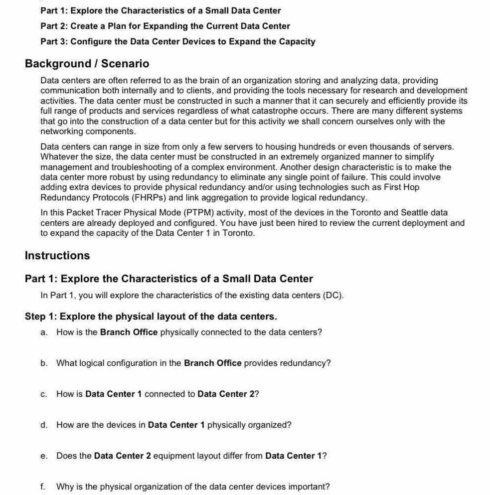
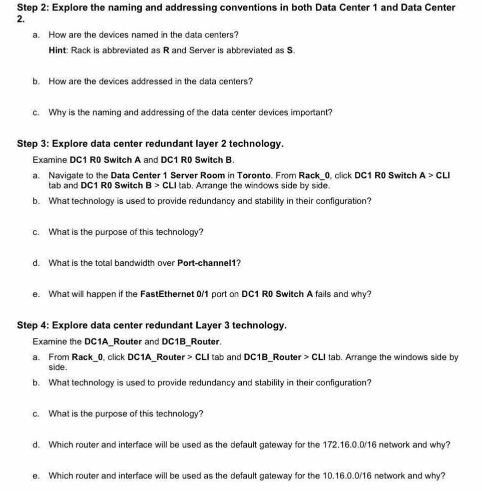
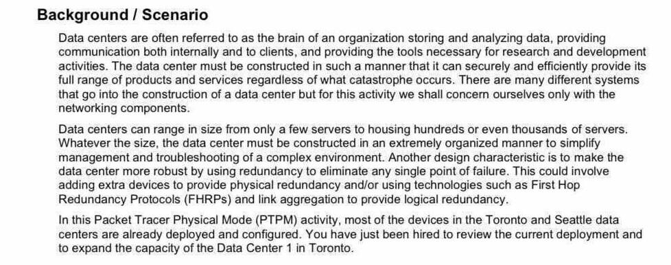
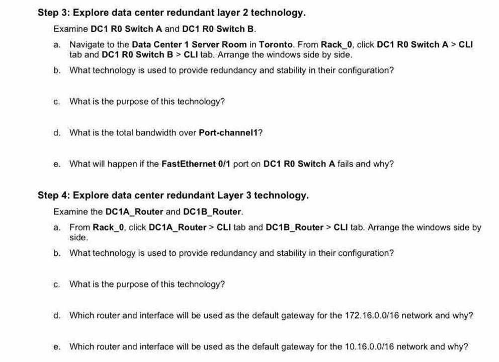
Background / Scenario Data centers are often referred to as the brain of an organization storing and analyzing data, providing communication both internally and to clients, and providing the tools necessary for research and development activities. The data center must be constructed in such a manner that it can securely and efficiently provide its full range of products and services regardless of what catastrophe occurs. There are many different systems that go into the construction of a data center but for this activity we shall concern ourselves only with the networking components. Data centers can range in size from only a few servers to housing hundreds or even thousands of servers. Whatever the size, the data center must be constructed in an extremely organized manner to simplify management and troubleshooting of a complex environment. Another design characteristic is to make the data center more robust by using redundancy to eliminate any single point of failure. This could involve adding extra devices to provide physical redundancy and/or using technologies such as First Hop Redundancy Protocols (FHRPs) and link aggregation to provide logical redundancy. In this packet Tracer Physical Mode (PTPM) activity, most of the devices in the Toronto and Seattle data centers are already deployed and configured. You have just been hired to review the current deployment and to expand the capacity of the Data Center 1 in Toronto. Step 3: Explore data center redundant layer 2 technology. Examine DC1 RO Switch A and DC1 RO Switch B. a. Navigate to the Data Center 1 Server Room in Toronto. From Rack_0, click DC1 RO Switch A > CLI tab and DC1 RO Switch B > CLI tab. Arrange the windows side by side. b. What technology is used to provide redundancy and stability in their configuration? C. What is the purpose of this technology? d. What is the total bandwidth over Port-channel? e. What will happen if the FastEthernet 0/1 port on DC1 RO Switch A fails and why? Step 4: Explore data center redundant Layer 3 technology. Examine the DC1A_Router and DC1B_Router. a. From Rack_0, click DC1A_Router > CLI tab and DC1B_Router > CLI tab. Arrange the windows side by side. b. What technology is used to provide redundancy and stability in their configuration? C. What is the purpose of this technology? d. Which router and interface will be used as the default gateway for the 172.16.0.0/16 network and why? e. Which router and interface will be used as the default gateway for the 10.16.0.0/16 network and why? Part 1: Explore the Characteristics of a Small Data Center Part 2: Create a Plan for Expanding the Current Data Center Part 3: Configure the Data Center Devices to Expand the Capacity Background / Scenario Data centers are often referred to as the brain of an organization storing and analyzing data, providing communication both internally and to clients, and providing the tools necessary for research and development activities. The data center must be constructed in such a manner that it can securely and efficiently provide its full range of products and services regardless of what catastrophe occurs. There are many different systems that go into the construction of a data center but for this activity we shall concer ourselves only with the networking components. Data centers can range in size from only a few servers to housing hundreds or even thousands of servers. Whatever the size, the data center must be constructed in an extremely organized manner to simplify management and troubleshooting of a complex environment. Another design characteristic is to make the data center more robust by using redundancy to eliminate any single point of failure. This could involve adding extra devices to provide physical redundancy and/or using technologies such as First Hop Redundancy Protocols (FHRPs) and link aggregation to provide logical redundancy. In this packet Tracer Physical Mode (PTPM) activity, most of the devices in the Toronto and Seattle data centers are already deployed and configured. You have just been hired to review the current deployment and to expand the capacity of the Data Center 1 in Toronto. Instructions Part 1: Explore the Characteristics of a Small Data Center In Part 1, you will explore the characteristics of the existing data centers (DC). Step 1: Explore the physical layout of the data centers. a. How is the Branch Office physically connected to the data centers? b. What logical configuration in the Branch Office provides redundancy? c. How is Data Center 1 connected to Data Center 2? d. How are the devices in Data Center 1 physically organized? e. Does the Data Center 2 equipment layout differ from Data Center 1? f. Why is the physical organization of the data center devices important? Step 2: Explore the naming and addressing conventions in both Data Center 1 and Data Center 2. a. How are the devices named in the data centers? Hint: Rack is abbreviated as R and Server is abbreviated as S. b. How are the devices addressed in the data centers? C. Why is the naming and addressing of the data center devices important? Step 3: Explore data center redundant layer 2 technology. Examine DC1 RO Switch A and DC1 RO Switch B. a. Navigate to the Data Center 1 Server Room in Toronto. From Rack_0, click DC1 RO Switch A > CLI tab and DC1 RO Switch B > CLI tab. Arrange the windows side by side. b. What technology is used to provide redundancy and stability in their configuration? C. What is the purpose of this technology? d. What is the total bandwidth over Port-channel1? e. What will happen if the FastEthernet 0/1 port on DC1 RO Switch A fails and why? Step 4: Explore data center redundant Layer 3 technology. Examine the DC1A_Router and DC1B_Router. a. From Rack_0, click DC1A_Router > CLI tab and DC1B_Router > CLI tab. Arrange the windows side by side. b. What technology is used to provide redundancy and stability in their configuration? c. What is the purpose of this technology? d. Which router and interface will be used as the default gateway for the 172.16.0.0/16 network and why? e. Which router and interface will be used as the default gateway for the 10.16.0.0/16 network and why? Background / Scenario Data centers are often referred to as the brain of an organization storing and analyzing data, providing communication both internally and to clients, and providing the tools necessary for research and development activities. The data center must be constructed in such a manner that it can securely and efficiently provide its full range of products and services regardless of what catastrophe occurs. There are many different systems that go into the construction of a data center but for this activity we shall concern ourselves only with the networking components. Data centers can range in size from only a few servers to housing hundreds or even thousands of servers. Whatever the size, the data center must be constructed in an extremely organized manner to simplify management and troubleshooting of a complex environment. Another design characteristic is to make the data center more robust by using redundancy to eliminate any single point of failure. This could involve adding extra devices to provide physical redundancy and/or using technologies such as First Hop Redundancy Protocols (FHRPs) and link aggregation to provide logical redundancy. In this packet Tracer Physical Mode (PTPM) activity, most of the devices in the Toronto and Seattle data centers are already deployed and configured. You have just been hired to review the current deployment and to expand the capacity of the Data Center 1 in Toronto. Step 3: Explore data center redundant layer 2 technology. Examine DC1 RO Switch A and DC1 RO Switch B. a. Navigate to the Data Center 1 Server Room in Toronto. From Rack_0, click DC1 RO Switch A > CLI tab and DC1 RO Switch B > CLI tab. Arrange the windows side by side. b. What technology is used to provide redundancy and stability in their configuration? C. What is the purpose of this technology? d. What is the total bandwidth over Port-channel? e. What will happen if the FastEthernet 0/1 port on DC1 RO Switch A fails and why? Step 4: Explore data center redundant Layer 3 technology. Examine the DC1A_Router and DC1B_Router. a. From Rack_0, click DC1A_Router > CLI tab and DC1B_Router > CLI tab. Arrange the windows side by side. b. What technology is used to provide redundancy and stability in their configuration? C. What is the purpose of this technology? d. Which router and interface will be used as the default gateway for the 172.16.0.0/16 network and why? e. Which router and interface will be used as the default gateway for the 10.16.0.0/16 network and why? Part 1: Explore the Characteristics of a Small Data Center Part 2: Create a Plan for Expanding the Current Data Center Part 3: Configure the Data Center Devices to Expand the Capacity Background / Scenario Data centers are often referred to as the brain of an organization storing and analyzing data, providing communication both internally and to clients, and providing the tools necessary for research and development activities. The data center must be constructed in such a manner that it can securely and efficiently provide its full range of products and services regardless of what catastrophe occurs. There are many different systems that go into the construction of a data center but for this activity we shall concer ourselves only with the networking components. Data centers can range in size from only a few servers to housing hundreds or even thousands of servers. Whatever the size, the data center must be constructed in an extremely organized manner to simplify management and troubleshooting of a complex environment. Another design characteristic is to make the data center more robust by using redundancy to eliminate any single point of failure. This could involve adding extra devices to provide physical redundancy and/or using technologies such as First Hop Redundancy Protocols (FHRPs) and link aggregation to provide logical redundancy. In this packet Tracer Physical Mode (PTPM) activity, most of the devices in the Toronto and Seattle data centers are already deployed and configured. You have just been hired to review the current deployment and to expand the capacity of the Data Center 1 in Toronto. Instructions Part 1: Explore the Characteristics of a Small Data Center In Part 1, you will explore the characteristics of the existing data centers (DC). Step 1: Explore the physical layout of the data centers. a. How is the Branch Office physically connected to the data centers? b. What logical configuration in the Branch Office provides redundancy? c. How is Data Center 1 connected to Data Center 2? d. How are the devices in Data Center 1 physically organized? e. Does the Data Center 2 equipment layout differ from Data Center 1? f. Why is the physical organization of the data center devices important? Step 2: Explore the naming and addressing conventions in both Data Center 1 and Data Center 2. a. How are the devices named in the data centers? Hint: Rack is abbreviated as R and Server is abbreviated as S. b. How are the devices addressed in the data centers? C. Why is the naming and addressing of the data center devices important? Step 3: Explore data center redundant layer 2 technology. Examine DC1 RO Switch A and DC1 RO Switch B. a. Navigate to the Data Center 1 Server Room in Toronto. From Rack_0, click DC1 RO Switch A > CLI tab and DC1 RO Switch B > CLI tab. Arrange the windows side by side. b. What technology is used to provide redundancy and stability in their configuration? C. What is the purpose of this technology? d. What is the total bandwidth over Port-channel1? e. What will happen if the FastEthernet 0/1 port on DC1 RO Switch A fails and why? Step 4: Explore data center redundant Layer 3 technology. Examine the DC1A_Router and DC1B_Router. a. From Rack_0, click DC1A_Router > CLI tab and DC1B_Router > CLI tab. Arrange the windows side by side. b. What technology is used to provide redundancy and stability in their configuration? c. What is the purpose of this technology? d. Which router and interface will be used as the default gateway for the 172.16.0.0/16 network and why? e. Which router and interface will be used as the default gateway for the 10.16.0.0/16 network and why
Step by Step Solution
There are 3 Steps involved in it
Step: 1

Get Instant Access to Expert-Tailored Solutions
See step-by-step solutions with expert insights and AI powered tools for academic success
Step: 2

Step: 3
Ace Your Homework with AI
Get the answers you need in no time with our AI-driven, step-by-step assistance
Get Started
Advances In Database Technology Edbt 88 International Conference On Extending Database Technology Venice Italy March 14 18 1988 Proceedings Lncs 303
Authors: Joachim W. Schmidt ,Stefano Ceri ,Michele Missikoff
1988th Edition
3540190740, 978-3540190745