Only individual part of the project needed
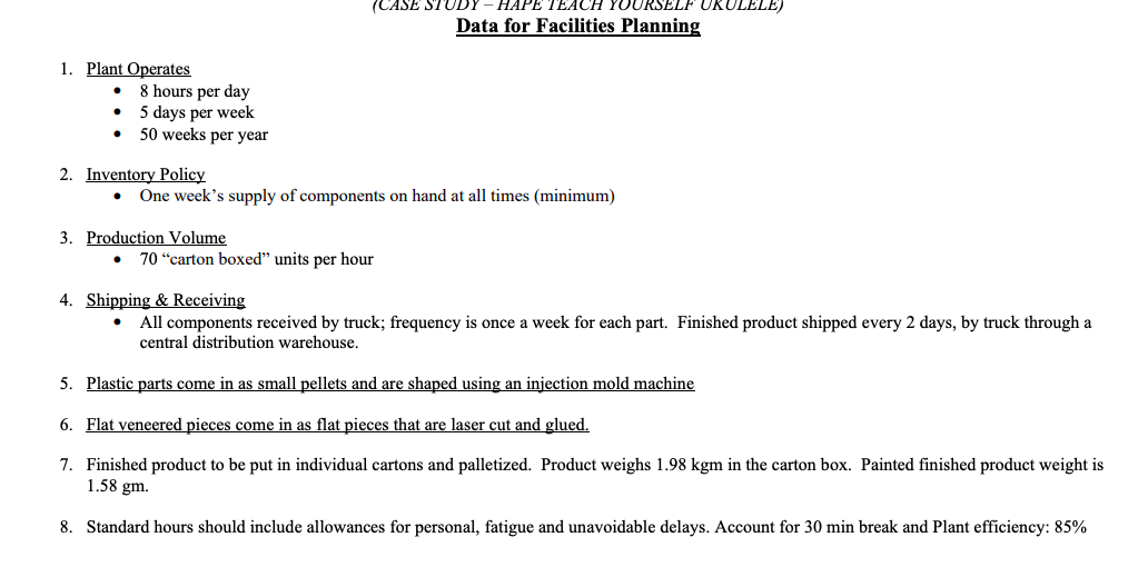
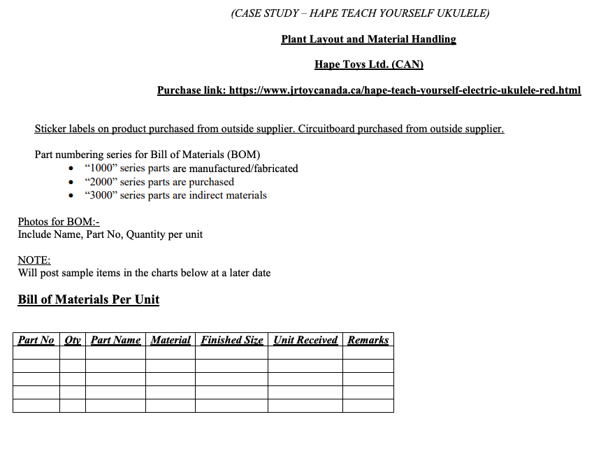
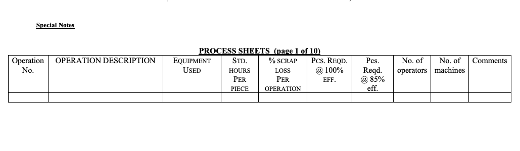


(CASE STUDY-HAPE TEACH YOURSELF UKULELE) Data for Facilities Planning . 1. Plant Operates 8 hours per day 5 days per week 50 weeks per year 2. Inventory Policy One week's supply of components on hand at all times (minimum) . 3. Production Volume 70 "carton boxed units per hour 4. Shipping & Receiving All components received by truck; frequency is once a week for each part. Finished product shipped every 2 days, by truck through a central distribution warehouse. . 5. Plastic parts come in as small pellets and are shaped using injection mold machine 6. Flat veneered pieces come in as flat pieces that are laser cut and glued. 7. Finished product to be put in individual cartons and palletized. Product weighs 1.98 kgm in the carton box. Painted finished product weight is 1.58 gm. 8. Standard hours should include allowances for personal, fatigue and unavoidable delays. Account for 30 min break and Plant efficiency: 85% (CASE STUDY - HAPE TEACH YOURSELF UKULELE) Plant Layout and Material Handling Hape Toys Ltd. (CAN) Purchase link: https://www.jrtoycanada.ca/hape-teach-yourself-electric-ukulele-red.html Sticker labels on product purchased from outside supplier. Circuitboard purchased from outside supplier. Part numbering series for Bill of Materials (BOM) 1000 series parts are manufactured/fabricated 2000 series parts are purchased "3000 series parts are indirect materials Photos for BOM:- Include Name, Part No, Quantity per unit NOTE: Will post sample items in the charts below at a later date Bill of Materials Per Unit Part No Oty Part Name Material Finished Size Unit Received Remarks Special Notes OPERATION DESCRIPTION Comments Operation No. PROCESS SHEETS (page 1 of 10 EQUIPMENT STD. % SCRAP PCS. REQD. USED HOURS LOSS @ 100% PER PER EFF. PIECE OPERATION Pcs. Reqd. @ 85% eff. No. of No. of operators machines Grading Group Report Fabrication 30 Assembly 25 Materials, Machines, Storage, Final Design (excl. Office + Parking) 20 Total 75 (30% of final grade) Individual Report Employee Services, Final Design (incl. Office + Parking) 12 Presentation 13 Total 25 (10% of final grade) Addendum Group Report Fabrication: Bill of materials* Production rate and available time calculation based on page 1 data of this document Parts requiring fabrication Each station/process is described in order: These are "modules in that you design a single complete module. For some modules (e.g., injection mold), multiple duplicates of the same module may be needed in the final design Consider what steps are needed and what the order of steps should be. E.g., metal products after cutting need inspecting. Rivetted products need deburring. Painted products need drying. Dried products need stickering. Therefore, inspecting, deburring, painting, drying, etc. all need a separate station AND an explanation what method, step and machine/tool will be used. Do not assume parts outputted from the first machine will automatically be ready for manual assembly. Each station process description includes*: Name of station input & output for each part that undergoes the process (e.g., input = "stamped, shape-inspected shell, output = "stamped, shape-inspected, riveted shell, process = "rivet machine"; 2nd example: input = "stamped, shape-inspected base", output = "stamped, shape-inspected, riveted base", process = "rivet machine"); photo of machine; method description; floorplan and "head-on" (vertical) layout diagrams (CASE STUDY - HAPE TEACH YOURSELF UKULELE) total time required for the process; speed of feed or conveyor belt, if applicable; Process charts* for each station process: Each manufactured part has a process chart that contains all the information in the sample on page 3 above but filled out completely. The sample above is only for reference. All floorplans and layout drawings: to scale and with distances, showing size of a person for reference; show which objects need power sources; show labelsames, sizes and distances of machines, stations, tables, scrap collection; show either conveyor that delivers input into and output out of this station, or input/output bins if transported via bins For all machines, include method description, layout diagram and details of machine specifications such as setup of machine, diagram showing shape it will cut or bend (if applicable), any jigs/fixtures For example, for laser cutting (if applicable), describe how the machine will be setup and diagrams of the pattern the laser cuts or etches Mention tools needed to support stations, e.g., forklifts, weight support machines/tools, with image and description Assembly: Takt time calculation based on page 1 data of this document High level process chart showing the inputted parts and assembly processes (excludes fabrication); assembly should not consist of only one process called "assembly" - it should be divided into multiple assembly processes For each assembly and process, summarize what parts are assembled packaged, how they are assembled and the total standard cycle time for the process based on the PTS charts and process charts in Appendices* Operators: number of operators required based on PTS charts and line balancing Line balancing: for each workstation, state cycle time based on PTS charts, number of operators, workstation-specific cycle time. Show 2-3 options for line balancing of workstations and explain which is selected and why. Workstation design, showing product flow For each workstation: WS number and which assembly/packaging processes it covers Input, output, required equipment, layout diagram Layout of assembly area, including input tables/bins/shelves, all WSs, conveyor belts, location of pallets of packaged product, human for size reference Operation process chart Materials, Machines, Storage: Scrap: calculate revised total units required per day = desired output / [(1-scrapPercentProcess 1)(1-scrapPercentProcess2)...], adjusted takt time and revised quantity for each part (given scrap rates of the manufacturing operations it requires) Calculate number of machines for each process given adjusted takt time and cycle time of the machine or MOST/ MTM analysis the work method to ensure sufficient machines Identify each type of part made by a machine separately, for clarity (e.g., Stamping - Base, Stamping - Shell) 5 (CASE STUDY - HAPE TEACH YOURSELF UKULELE) Do not assume 1 machine is sufficient. If injection mold machine(s) are used to make 6 parts, can use a single machine only if the total cycle time for all 6 parts is less than the adjusted takt time Calculate number of employees in fabrication and assembly (does not include office support staff/admin) Activity relationship analysis and chart Material handling Warehouse operations Shipping, receiving, docks Storage: name of item, size, volume, quantity, storage area needed Design of storage area Final design of factory, excluding office space, parking: Diagram including all modules for fabrication, assembly, shipping, receiving, storage, material handling, all elements inside factory excluding office as detailed views (not a solid square with the label stamping room floorplan of the room including individual machines, storage bins, tables, must be visible), flow of parts (arrows showing the flow of a part). Legend & annotations required to identify machines, assembly workers, etc. Individual Report Employee Services, Parking: Calculation of machine space utilization Personnel, services areas and their design Calculate total number of personnel, includes office support staff/admin/etc. Design of office space and floorplan Parking design Parking design indicating individual car spots, car spot types, walkways, calculations to determine optimal parking design Final design of factory, office space, parking added Diagram including all modules (employee services, parking, included) as detailed views (not a solid square with the label "stamping room floorplan of the room including individual machines, storage bins, tables, parking spaces must be visible), flow of parts (arrows showing the flow of a part). Individual Presentation The group decides what each individual will present * Full Bill of materials, process sheets and Predetermined Time System (MOST or MTM) analyses are placed in Appendices only and contain more details. A summary and excerpt are placed in the main document. (CASE STUDY-HAPE TEACH YOURSELF UKULELE) Data for Facilities Planning . 1. Plant Operates 8 hours per day 5 days per week 50 weeks per year 2. Inventory Policy One week's supply of components on hand at all times (minimum) . 3. Production Volume 70 "carton boxed units per hour 4. Shipping & Receiving All components received by truck; frequency is once a week for each part. Finished product shipped every 2 days, by truck through a central distribution warehouse. . 5. Plastic parts come in as small pellets and are shaped using injection mold machine 6. Flat veneered pieces come in as flat pieces that are laser cut and glued. 7. Finished product to be put in individual cartons and palletized. Product weighs 1.98 kgm in the carton box. Painted finished product weight is 1.58 gm. 8. Standard hours should include allowances for personal, fatigue and unavoidable delays. Account for 30 min break and Plant efficiency: 85% (CASE STUDY - HAPE TEACH YOURSELF UKULELE) Plant Layout and Material Handling Hape Toys Ltd. (CAN) Purchase link: https://www.jrtoycanada.ca/hape-teach-yourself-electric-ukulele-red.html Sticker labels on product purchased from outside supplier. Circuitboard purchased from outside supplier. Part numbering series for Bill of Materials (BOM) 1000 series parts are manufactured/fabricated 2000 series parts are purchased "3000 series parts are indirect materials Photos for BOM:- Include Name, Part No, Quantity per unit NOTE: Will post sample items in the charts below at a later date Bill of Materials Per Unit Part No Oty Part Name Material Finished Size Unit Received Remarks Special Notes OPERATION DESCRIPTION Comments Operation No. PROCESS SHEETS (page 1 of 10 EQUIPMENT STD. % SCRAP PCS. REQD. USED HOURS LOSS @ 100% PER PER EFF. PIECE OPERATION Pcs. Reqd. @ 85% eff. No. of No. of operators machines Grading Group Report Fabrication 30 Assembly 25 Materials, Machines, Storage, Final Design (excl. Office + Parking) 20 Total 75 (30% of final grade) Individual Report Employee Services, Final Design (incl. Office + Parking) 12 Presentation 13 Total 25 (10% of final grade) Addendum Group Report Fabrication: Bill of materials* Production rate and available time calculation based on page 1 data of this document Parts requiring fabrication Each station/process is described in order: These are "modules in that you design a single complete module. For some modules (e.g., injection mold), multiple duplicates of the same module may be needed in the final design Consider what steps are needed and what the order of steps should be. E.g., metal products after cutting need inspecting. Rivetted products need deburring. Painted products need drying. Dried products need stickering. Therefore, inspecting, deburring, painting, drying, etc. all need a separate station AND an explanation what method, step and machine/tool will be used. Do not assume parts outputted from the first machine will automatically be ready for manual assembly. Each station process description includes*: Name of station input & output for each part that undergoes the process (e.g., input = "stamped, shape-inspected shell, output = "stamped, shape-inspected, riveted shell, process = "rivet machine"; 2nd example: input = "stamped, shape-inspected base", output = "stamped, shape-inspected, riveted base", process = "rivet machine"); photo of machine; method description; floorplan and "head-on" (vertical) layout diagrams (CASE STUDY - HAPE TEACH YOURSELF UKULELE) total time required for the process; speed of feed or conveyor belt, if applicable; Process charts* for each station process: Each manufactured part has a process chart that contains all the information in the sample on page 3 above but filled out completely. The sample above is only for reference. All floorplans and layout drawings: to scale and with distances, showing size of a person for reference; show which objects need power sources; show labelsames, sizes and distances of machines, stations, tables, scrap collection; show either conveyor that delivers input into and output out of this station, or input/output bins if transported via bins For all machines, include method description, layout diagram and details of machine specifications such as setup of machine, diagram showing shape it will cut or bend (if applicable), any jigs/fixtures For example, for laser cutting (if applicable), describe how the machine will be setup and diagrams of the pattern the laser cuts or etches Mention tools needed to support stations, e.g., forklifts, weight support machines/tools, with image and description Assembly: Takt time calculation based on page 1 data of this document High level process chart showing the inputted parts and assembly processes (excludes fabrication); assembly should not consist of only one process called "assembly" - it should be divided into multiple assembly processes For each assembly and process, summarize what parts are assembled packaged, how they are assembled and the total standard cycle time for the process based on the PTS charts and process charts in Appendices* Operators: number of operators required based on PTS charts and line balancing Line balancing: for each workstation, state cycle time based on PTS charts, number of operators, workstation-specific cycle time. Show 2-3 options for line balancing of workstations and explain which is selected and why. Workstation design, showing product flow For each workstation: WS number and which assembly/packaging processes it covers Input, output, required equipment, layout diagram Layout of assembly area, including input tables/bins/shelves, all WSs, conveyor belts, location of pallets of packaged product, human for size reference Operation process chart Materials, Machines, Storage: Scrap: calculate revised total units required per day = desired output / [(1-scrapPercentProcess 1)(1-scrapPercentProcess2)...], adjusted takt time and revised quantity for each part (given scrap rates of the manufacturing operations it requires) Calculate number of machines for each process given adjusted takt time and cycle time of the machine or MOST/ MTM analysis the work method to ensure sufficient machines Identify each type of part made by a machine separately, for clarity (e.g., Stamping - Base, Stamping - Shell) 5 (CASE STUDY - HAPE TEACH YOURSELF UKULELE) Do not assume 1 machine is sufficient. If injection mold machine(s) are used to make 6 parts, can use a single machine only if the total cycle time for all 6 parts is less than the adjusted takt time Calculate number of employees in fabrication and assembly (does not include office support staff/admin) Activity relationship analysis and chart Material handling Warehouse operations Shipping, receiving, docks Storage: name of item, size, volume, quantity, storage area needed Design of storage area Final design of factory, excluding office space, parking: Diagram including all modules for fabrication, assembly, shipping, receiving, storage, material handling, all elements inside factory excluding office as detailed views (not a solid square with the label stamping room floorplan of the room including individual machines, storage bins, tables, must be visible), flow of parts (arrows showing the flow of a part). Legend & annotations required to identify machines, assembly workers, etc. Individual Report Employee Services, Parking: Calculation of machine space utilization Personnel, services areas and their design Calculate total number of personnel, includes office support staff/admin/etc. Design of office space and floorplan Parking design Parking design indicating individual car spots, car spot types, walkways, calculations to determine optimal parking design Final design of factory, office space, parking added Diagram including all modules (employee services, parking, included) as detailed views (not a solid square with the label "stamping room floorplan of the room including individual machines, storage bins, tables, parking spaces must be visible), flow of parts (arrows showing the flow of a part). Individual Presentation The group decides what each individual will present * Full Bill of materials, process sheets and Predetermined Time System (MOST or MTM) analyses are placed in Appendices only and contain more details. A summary and excerpt are placed in the main document