

Question
Open the problem 9 subcircuit. Many vehicles are designed such that if you turn on the ignition switch without having your seatbelt buckled, a warning
- Open the problem 9 subcircuit. Many vehicles are designed such that if you turn on the ignition switch without having your seatbelt buckled, a warning chime sounds for about 4 seconds, and a light in the dashboard turns on. Design a circuit that accomplishes this task.
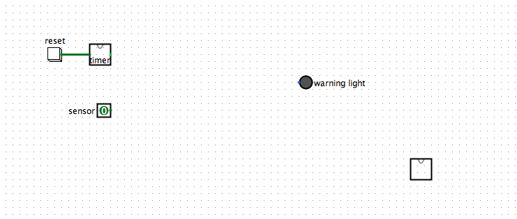
In the Logisim file, you will find two inputs for the circuit: a seatbelt sensor represented by an input pin, and a timer unit. There is one output: an LED which would be placed in the cars dashboard.
We will expect the seatbelt sensor to generate a LOW value if the seatbelt is not buckled, and a HIGH value if it is buckled. The LED requires a HIGH value to make it light.
Specifically the circuit should be designed to do the following:
- When the ignition switch is turned on, if the seatbelt is NOT buckled, then the warning light should turn on for 4 seconds and then turn off.
- After 4 seconds, the light will stay off whether the seatbelt is buckled or not.
- During the first 4 seconds, if the seatbelt is buckled then the light should turn off. (If it is unbuckled again the light will come back on).
For this problem you will need to ensure that the Ticks Enabled option under the Simulate menu is checked. Also under the Simulate menu, ensure that Tick Frequency is set to 1 Hz. Pressing the Reset button in the circuit will be equivalent to turning the cars ignition switch on. You can simulate buckling and unbuckling the seatbelt by toggling the sensor input pin. The timer unit is already designed so that when the circuit is powered on, it will output a HIGH value for about 4 seconds, and then it will change it output to LOW.
Begin your design by filling in the truth table below to show the output expected from the circuit.
| Timer | Sensor | LED |
| 1 | 0 |
|
| 1 | 1 |
|
| 0 | X |
|
Secondly, write the Boolean algebra expression for the circuit represented in your truth table:
Enter your expression here:
|
|
Finally, add gates to the circuit and connect the wires to construct the circuit.
Make sure that you test the circuit after building it to verify that it works correctly.
reset imer Owarning light sensor O
Step by Step Solution
There are 3 Steps involved in it
Step: 1

Get Instant Access to Expert-Tailored Solutions
See step-by-step solutions with expert insights and AI powered tools for academic success
Step: 2

Step: 3
Ace Your Homework with AI
Get the answers you need in no time with our AI-driven, step-by-step assistance
Get Started
The Structure Of The Relational Database Model
Authors: Jan Paredaens ,Paul De Bra ,Marc Gyssens ,Dirk Van Gucht
1st Edition
3642699588, 978-3642699580