Answered step by step
Verified Expert Solution
Question
1 Approved Answer
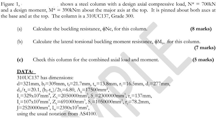
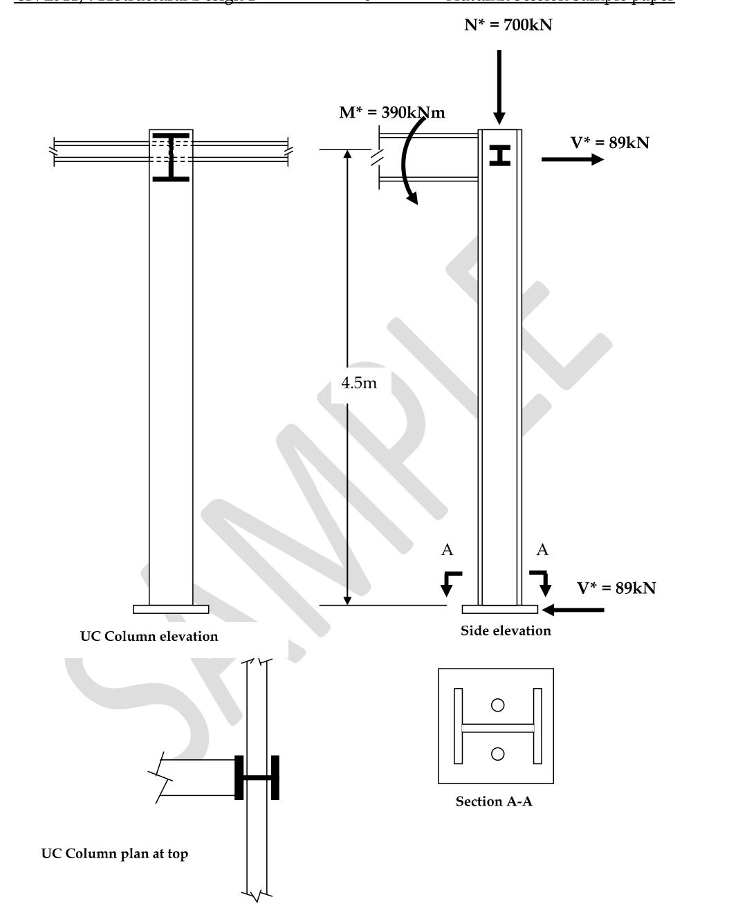
Figure 1, shows a steel column with a design axial compressive load, N* = 700kN and a design moment, M* = 390kNm about the


Figure 1, shows a steel column with a design axial compressive load, N* = 700kN and a design moment, M* = 390kNm about the major axis at the top. It is pinned about both axes at the base and at the top. The column is a 310UC137, Grade 300. (a) Calculate the buckling resistance, oNc, for this column. (8 marks) (b) Calculate the lateral torsional buckling moment resistance, M, for this column. (7 marks) (5 marks) (c) Check this column for the combined axial load and moment. DATA: 310UC137 has dimensions: d=321mm, b=309mm, t-21.7mm, t=13.8mm, r=16.5mm, d,=277mm, d/t=20.1, (b-t)/2t 6.80, A=17500mm, I=329x10 mm, Z=2050000mm, S=2300000mm, r=137mm, I=107x10 mm, Z=691000mm, S=1050000mm, r=78.2mm, J=2520000mm, L=2390x10 mm", using the usual notation from AS4100. UC Column elevation UC Column plan at top M* = 390kNm 4.5m N* = 700kN A I YAMAN V* = 89kN A 7 V* = 89kN Side elevation Section A-A
Step by Step Solution
★★★★★
3.50 Rating (150 Votes )
There are 3 Steps involved in it
Step: 1
a To calculate the buckling resistance Nc for the column we can use the Euler buckling equation Given data Design axial compressive load N 700 kN Colu...
Get Instant Access to Expert-Tailored Solutions
See step-by-step solutions with expert insights and AI powered tools for academic success
Step: 2

Step: 3

Ace Your Homework with AI
Get the answers you need in no time with our AI-driven, step-by-step assistance
Get Started


