

Question: Part 1 (Scenario 1) Note; To do this assinment, we have to use the codes in the below named (firstnode and sixth node). but we
Part 1 (Scenario 1)
Note; To do this assinment, we have to use the codes in the below named (firstnode and sixth node). but we have to edit the codes when doing the Scenario1 and Scenario 2. Also when doing this assignment, it should be done with C code, At the same time, For this assignment we need to use Cooja Application on Docker.
Introduction
For the 1st assignment of the Computer Networks course, we performed packet forwarding in a line topology. Out of the 3 firmware in the 1st assignment, the firmware installed on node 1 and node 6 will be used in the 2nd assignment. In assignment 2, you are expected to intervene, observe and report on the routing algorithm using different metrics during packet forwarding in a wireless sensor network consisting of several nodes towards the border-router
Observation and Coding Process
In Industrial Wireless Sensor Networks, RPL (the lite version RPL-Lite will be used in the assignment) is the defacto routing protocol.
The RPL routing algorithm uses a variable called rank, which stands for link quality, to assign paths to packets. In the RPL algorithm, packets traveling from end nodes towards the root node will prefer the father of the node visited along the way for the next hop. In short, RPL works on the principle of choosing the father with the highest quality link until it reaches the root. (See: https://docs.contiki-ng.org/en/develop/doc/programming/RPL.html)
The rank variable can be created based on various criteria. Example criteria: Min. hop count, RSSI-based, Random, Authorization-based, Equal Battery Consumption-based, etc.
In order for developers to run the RPL routing algorithm with different criteria or combinations of criteria of their own design, it is sufficient to implement the objective function-of API in the code stack. There are 2 samples in the Contiki-os/oset/routing/rpl-lite directory. Note the source code file names in the /rpl-lite directory. You can recognize these files by the "of" objective function tag. These are:
1. Contiki-ng/oset/routing/rpl-lite/rpl-mrhof.c
2. Contiki-ng/oset/routing/rpl-lite/rpl-of0.c
These source code files and the method and variable naming in them are well documented by the authors. It will be useful for you to implement your own metric. You can create your own " of " file from scratch. Or you can copy the existing sample of files, rename them and change the appropriate places in the code. The "of" file names to be submitted should be as follows.
1. contiki-ng/oset/routing/rpl-lite/rpl-of-minhop.c
2. contiki-ng/oset/routing/rpl-lite/rpl-of-rssi.c
3. contiki-ng/oset/routing/rpl-lite/rpl-of-minhop-vs-rssi.c
You need to tell the contiki-ng operating system which "of " to use when the contiki-ng operating system stands up by setting it in the contiki-ng/oset/routing/rpl-lite/rpl-conf.h file.
Related line in contiki-ng/oset/routing/rpl-lite/rpl-conf.h: (line 90)
/* * The set of objective functions supported at runtime. Nodes are only * able to join instances that advertise an OF in this set. To include * both OF0 and MRHOF, use {&rpl_of0, &rpl_mrhof}. */ #ifdef RPL_CONF_SUPPORTED_OFS #define RPL_SUPPORTED_OFS RPL_CONF_SUPPORTED_OFS #else /* RPL_CONF_SUPPORTED_OFS */ //1. Example objective func. set: rpl-mrhof.c #define RPL_SUPPORTED_OFS {&rpl_mrhof} #endif /* RPL_CONF_SUPPORTED_OFS */
Suppose you have defined your own of named my_of.c. The corresponding set line in the code block above should be as follows: #define RPL_SUPPORTED_OFS {&my_of} All objective function files must implement methods and variables with the same names in the examples. You can see that the method and structure names used in both examples "of" are the same.
Once the routing algorithm is configured to work according to the given metric value, you need to run the results according to the following scenarios.
Assignment Scenarios
Before starting the scenarios, you need to create firmware in the network that continuously sends packets to the border-router to test the routing algorithm that works according to your criteria. We will reuse the firmware files you coded in Assignment.1 by giving them a different name:
firstnode.c in Assignment.1 (change to) sayac.c in Assignment.2 sixthnode.c used in Assignment.1 (change to) trafo.c in Assignment.2
Scenario 1 - Routing with Minimum Hop Count Criteria
9 pieces of firmware named sayac.c and 1 piece of firmware named trafo.c are created. As shown in the figure below, node 10 (in the border-router role) is running trafo.c and the other nodes are running sayac.c. (Node number indices and order do not matter in this assignment. The distances between nodes must be exactly the same as in the figure). Hop count means the number of links that packets hop before reaching the root. For example, the path 1-4-7-10 in Figure 1 has 3 hops.
For each node, asking how many hops away its neighbors are from the root node and choosing the min. one of them is the most important part you need to code. For example, in Figure 1, node 1 must first find out how many hops each of its neighbors are from the root before choosing between nodes 2 and 4, and then decide on node 4 as the father node. Node 2 is 6 hops from the root and node 4 is 2 hops from the root. If "of" is coded correctly, the typical behavior expected from the algorithm should be as follows:
Packets from node 1_ to node 10_ are expected to prefer the route 1-4-7-10, which is the path with the minimum hop count. It should not prefer the route 1-2-8-3-5-6-9-10 (7 hops). With the routing criterion you defined, the simulation is run at the fastest speed (speed 1000x) for 2 minutes. The path marked in red should not have been used at all during this time.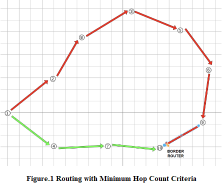
If, while the simulation is running, when you hold node 10_ with the mouse and drag it to the region shown in Figure 2, the packets now prefer the path indicated by the red arrow; it means that "of" is working correctly. The new min. hop path is now 1-2-10 (2 hops). In comparison, 1-4-7-10 (3 hops) is expected not to be preferred by the algorithm since it has more hops. 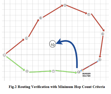
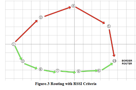
Scenario 2 - Routing with RSSI Criteria
9 pieces of firmware named sayac.c and 1 piece of firmware named trafo.c are created. As shown in the figure below, node 10 (in the border-router role) is running trafo.c and the other nodes are running sayac.c. (Node number indices and order do not matter in this assignment. The distances between the nodes must be exactly the same as in the figure). RSSI-Received Signal Strength Indication stands for Received Signal Strength Indication.
For each node, the process of asking the RSSI information of its neighbors and choosing the maximum one among them is the most important part you need to code. For example, in Fig.3, node 1 has to find out the RSSI information of its neighbors before choosing between nodes 2 and 3, and then decide on node 3 as the father node. Since d is distance and d1-3
If "of" is coded correctly, the algorithm selects the nodes with high signal strength as the father nodes and the packets are transmitted through the selected father nodes while the packets are traveling from node 1 to node 10.
As can be seen in Figure 3, the nodes on the green route 1-3-8-7-9-6-10 are closer to each other, so it is expected that nodes will prefer this route since the signal strength (RSSI) of the nodes closer to each other will be higher. Route 1-2-4-5-10 should not be preferred. With the RSSI routing criterion you defined, the simulation is run at the fastest speed (speed 1000x) for 2 minutes. In the elapsed time, the path marked in red should not be used at all.
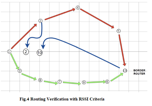
If, while the simulation is running, when you hold the mouse on nodes 2 and 10 (blue arrow) as shown in Figure 4 and move it to the marked area, the packets now prefer the 1-2-10 path, then "of" is working correctly.
Scenario 3 RSSI and Min. Hop Count Comparison
You need to compare these 2 coded metric values on the basis of energy consumption. For this, create a file named Makefile in your firmware folder (the folder where sayac.c and trafo.c are located), write the following rules in it and save it:
CONTIKI_PROJECT = example all: $(CONTIKI_PROJECT) CONTIKI = ../... include $(CONTIKI)/Makefile.dir-variables MODULES += $(CONTIKI_NG_SERVICES_DIR)/simple-energest include $(CONTIKI)/Makefile.include
** Your firmware folder must be under /contiki-ng/examples. Otherwise you will need to edit the variable in the Makefile rule file that refers to the CONTIKI path.
Let's move on to the scenario after activating the module to keep track of the energy consumed.
15 (3x5) pieces of firmware named sayac.c and 1 piece of firmware named trafo are created. With the routing criteria you defined, the simulation is run at the fastest speed (speed 1000x) for 2 minutes for each of them. As shown in the figure below, trafo.c is running on the rightmost node 25 and sayac.c is running on the other nodes.
(Node number indices do not matter in this assignment. The distances between the nodes must be exactly the same as in the figure).
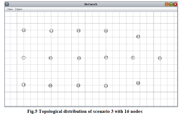
To summarize scenario 3, it consists of running the routing algorithm based on min_hop and RSSI, already prepared in scenarios 1 and 2, sequentially in a topology with energy module and different number of nodes. There is no coding process. In contiki-ng/oset/routing/rpl-lite/rpl-conf.h every 2 "of" must be set in sequence.
-----------------------------------
Note: The firstnode.c code I used for the 1st assignment can be used for the sayac.c in this assignment.
firstnode.c
#include "contiki.h" #include "net/routing/routing.h" #include "netetstack.h" #include "net/ipv6/simple-udp.h" #include
#include "sys/log.h" #define LOG_MODULE "App" #define LOG_LEVEL LOG_LEVEL_INFO
#define WITH_SERVER_REPLY 1 #define UDP_CLIENT_PORT 8765 #define UDP_SERVER_PORT 5678
static struct simple_udp_connection udp_conn;
PROCESS(udp_server_process, "UDP server"); AUTOSTART_PROCESSES(&udp_server_process); static void udp_rx_callback(struct simple_udp_connection *c, const uip_ipaddr_t *sender_addr, uint16_t sender_port, const uip_ipaddr_t *receiver_addr, uint16_t receiver_port, const uint8_t *data, uint16_t datalen) { LOG_INFO("Received request '%.*s' from ", datalen, (char *) data); char control[] = "LIGHT6: TURNED_ON"; if(strcmp((char *)data,control) == 0){ LOG_INFO("LIGHT6 SUCCESSFULLY TURNED_ON "); } else{ LOG_INFO("LIGHT6 PROCESS FAILED "); } LOG_INFO_6ADDR(sender_addr); LOG_INFO_(" "); char resp[] = "LIGHT6: TURN_ON"; #if WITH_SERVER_REPLY /* send back the same string to the client as an echo reply */ LOG_INFO("Sending response. "); simple_udp_sendto(&udp_conn, resp, strlen(resp), sender_addr); #endif /* WITH_SERVER_REPLY */ } PROCESS_THREAD(udp_server_process, ev, data) { PROCESS_BEGIN();
/* Initialize DAG root */ NETSTACK_ROUTING.root_start();
/* Initialize UDP connection */ simple_udp_register(&udp_conn, UDP_SERVER_PORT, NULL, UDP_CLIENT_PORT, udp_rx_callback);
PROCESS_END(); } ---------------------------------------
Note: The sixthnode.c code I used for the 1st assignment can be used for the trafo.c in this assignment.
sxthnode.c
#include "contiki.h" #include "net/routing/routing.h" #include "random.h" #include "netetstack.h" #include "net/ipv6/simple-udp.h" #include
#include "sys/log.h" #define LOG_MODULE "App" #define LOG_LEVEL LOG_LEVEL_INFO
#define WITH_SERVER_REPLY 1 #define UDP_CLIENT_PORT 8765 #define UDP_SERVER_PORT 5678
#define SEND_INTERVAL (60 * CLOCK_SECOND)
static struct simple_udp_connection udp_conn; static uint32_t rx_count = 0; static uint32_t temp = 0; PROCESS(udp_client_process, "UDP client"); AUTOSTART_PROCESSES(&udp_client_process); static void udp_rx_callback(struct simple_udp_connection *c, const uip_ipaddr_t *sender_addr, uint16_t sender_port, const uip_ipaddr_t *receiver_addr, uint16_t receiver_port, const uint8_t *data, uint16_t datalen) { char control[] = "LIGHT6: TURN_ON"; if(strcmp((char *)data,control) == 0){ temp = 1 ; } else{ temp = 0; } LOG_INFO("Received response '%.*s' from ", datalen, (char *) data); LOG_INFO_6ADDR(sender_addr); #if LLSEC802154_CONF_ENABLED LOG_INFO_(" LLSEC LV:%d", uipbuf_get_attr(UIPBUF_ATTR_LLSEC_LEVEL)); #endif LOG_INFO_(" "); rx_count++; } PROCESS_THREAD(udp_client_process, ev, data) { static struct etimer periodic_timer; static char str[32]; uip_ipaddr_t dest_ipaddr; static uint32_t tx_count; static uint32_t missed_tx_count; PROCESS_BEGIN();
/* Initialize UDP connection */ simple_udp_register(&udp_conn, UDP_CLIENT_PORT, NULL, UDP_SERVER_PORT, udp_rx_callback);
etimer_set(&periodic_timer, random_rand() % SEND_INTERVAL); while(1) { PROCESS_WAIT_EVENT_UNTIL(etimer_expired(&periodic_timer));
if(NETSTACK_ROUTING.node_is_reachable() && NETSTACK_ROUTING.get_root_ipaddr(&dest_ipaddr)) {
/* Print statistics every 10th TX */ if(tx_count % 10 == 0) { LOG_INFO("Tx/Rx/MissedTx: %" PRIu32 "/%" PRIu32 "/%" PRIu32 " ", tx_count, rx_count, missed_tx_count); } if(temp == 1){ LOG_INFO_6ADDR(&dest_ipaddr); LOG_INFO_(" "); snprintf(str, sizeof(str), "LIGHT6: TURNED_ON"); simple_udp_sendto(&udp_conn, str, strlen(str), &dest_ipaddr); tx_count++; } else{ LOG_INFO_6ADDR(&dest_ipaddr); LOG_INFO_(" "); snprintf(str, sizeof(str), "WRONG REQ"); simple_udp_sendto(&udp_conn, str, strlen(str), &dest_ipaddr); tx_count++; } } else { LOG_INFO("Not reachable yet "); if(tx_count > 0) { missed_tx_count++; } }
/* Add some jitter */ etimer_set(&periodic_timer, SEND_INTERVAL - CLOCK_SECOND + (random_rand() % (2 * CLOCK_SECOND))); }
PROCESS_END(); }
Thanks
Figure.1 Routing with Minimum Hop Count Criteria Fig.2 Routing Verification with Minimum Hop Count Criteria Figure.3 Routing with RSSI Criteria Fig.4 Routing Verification with RSSI Criteria Fig.5 Topological distribution of scenario 3 with 16 nodes
Step by Step Solution
There are 3 Steps involved in it

Get step-by-step solutions from verified subject matter experts