

Question: Part 1 - You will use the Arduino analogWrite function to control the brightness of LEDs, display the analog pin voltage, and the current through
Part 1 - You will use the Arduino analogWrite function to control the brightness of LEDs, display the analog pin voltage, and the current through the led. This sketch uses the analogWrite function to vary the voltage on the pins. The Serial library functions are used to display the analog voltages on the Serial Monitor.
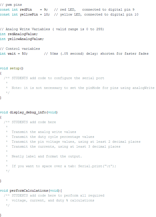
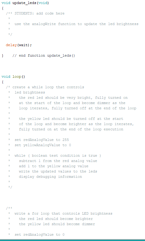
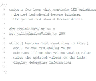
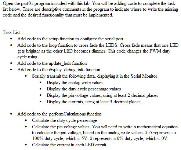
J/ pwm pins const int redPin = 9; const int yellowPin = 10; // red LED, connected to digital pin 9 // yellow LED, connected to digital pin 10 // Analog Write Variables ( valid range is 0 to 255) int redAnalogValue; int yellowAnalogValue; Jl Control variables int wait = 50; // 50ms (.05 second) delay; shorten for faster fades void setup() { /** STUDENTS add code to configure the serial port Note: it is not necessary to set the pinMode for pins using analogWrite */ } void display_debug_info(void) { /** STUDENTS add code here * Transmit the analog write values Transmit the duty cycle percentage values Transmit the pin voltage values, using at least 2 decimal places Transmit the currents, using at least 3 decimal places Neatly label and format the output. * If you want to space over a tab: Serial.print("\t"); */ } void performCalculations (void) { /** STUDENTS add code here to perform all required voltage, current, and duty calculations } void update_leds (void) { /** STUDENTS: add code here * use the analogWrite function to update the led brightness * * delay (wait); } // end function update_leds () void loop() { /* create a while loop that controls led brightness the red led should be very bright, fully turned on at the start of the loop and become dimmer as the loop iterates, fully turned off at the end of the loop * * * the yellow led should be turned off at the start of the loop and become brighter as the loop iterates, fully turned on at the end of the loop execution * * * set redAnalogValue to 255 set yellowAnalogValue to O * * * * while ( boolean test condition is true) subtract 1 from the red analog value add 1 to the yellow analog value write the updated values to the leds display debugging information * * * write a for loop that controls LED brightness the red led should become brighter the yellow led should become dimmer * * set redAnalogValue to 0 * write a for loop that controls LED brightnes the red led should become brighter the yellow led should become dimmer set redAnalogValue to O set yellowAnalogValue to 255 * * while ( boolean test condition is true) add 1 to the red analog value subtract 1 from the yellow analog value write the updated values to the leds display debugging information * Open the part01 program included with this lab. You will be adding code to complete the task list below. There are descriptive comments in the program to indicate where to write the missing code and the desired functionality that must be implemented. Task List Add code to the setup function to configure the serial port Add code to the loop function to cross fade the LEDS. Cross fade means that one LED gets brighter as the other LED becomes dimmer. This code changes the PWM duty cycle using Add code to the update_leds function Add code to the display_debug_info function Serially transmit the following data, displaying it in the Serial Monitor Display the analog write values Display the duty cycle percentage values Display the pin voltage values, using at least 2 decimal places Display the currents, using at least 3 decimal places Add code to the performCalculations function Calculate the duty cycle percentage Calculate the pin voltage values. You will need to write a mathematical equation to calculate the pin voltage, based on the analog write values. 255 represents a 100% duty cycle, which is 5V. O represents a 0% duty cycle, which is OV. Calculate the current in each LED circuit. J/ pwm pins const int redPin = 9; const int yellowPin = 10; // red LED, connected to digital pin 9 // yellow LED, connected to digital pin 10 // Analog Write Variables ( valid range is 0 to 255) int redAnalogValue; int yellowAnalogValue; Jl Control variables int wait = 50; // 50ms (.05 second) delay; shorten for faster fades void setup() { /** STUDENTS add code to configure the serial port Note: it is not necessary to set the pinMode for pins using analogWrite */ } void display_debug_info(void) { /** STUDENTS add code here * Transmit the analog write values Transmit the duty cycle percentage values Transmit the pin voltage values, using at least 2 decimal places Transmit the currents, using at least 3 decimal places Neatly label and format the output. * If you want to space over a tab: Serial.print("\t"); */ } void performCalculations (void) { /** STUDENTS add code here to perform all required voltage, current, and duty calculations } void update_leds (void) { /** STUDENTS: add code here * use the analogWrite function to update the led brightness * * delay (wait); } // end function update_leds () void loop() { /* create a while loop that controls led brightness the red led should be very bright, fully turned on at the start of the loop and become dimmer as the loop iterates, fully turned off at the end of the loop * * * the yellow led should be turned off at the start of the loop and become brighter as the loop iterates, fully turned on at the end of the loop execution * * * set redAnalogValue to 255 set yellowAnalogValue to O * * * * while ( boolean test condition is true) subtract 1 from the red analog value add 1 to the yellow analog value write the updated values to the leds display debugging information * * * write a for loop that controls LED brightness the red led should become brighter the yellow led should become dimmer * * set redAnalogValue to 0 * write a for loop that controls LED brightnes the red led should become brighter the yellow led should become dimmer set redAnalogValue to O set yellowAnalogValue to 255 * * while ( boolean test condition is true) add 1 to the red analog value subtract 1 from the yellow analog value write the updated values to the leds display debugging information * Open the part01 program included with this lab. You will be adding code to complete the task list below. There are descriptive comments in the program to indicate where to write the missing code and the desired functionality that must be implemented. Task List Add code to the setup function to configure the serial port Add code to the loop function to cross fade the LEDS. Cross fade means that one LED gets brighter as the other LED becomes dimmer. This code changes the PWM duty cycle using Add code to the update_leds function Add code to the display_debug_info function Serially transmit the following data, displaying it in the Serial Monitor Display the analog write values Display the duty cycle percentage values Display the pin voltage values, using at least 2 decimal places Display the currents, using at least 3 decimal places Add code to the performCalculations function Calculate the duty cycle percentage Calculate the pin voltage values. You will need to write a mathematical equation to calculate the pin voltage, based on the analog write values. 255 represents a 100% duty cycle, which is 5V. O represents a 0% duty cycle, which is OV. Calculate the current in each LED circuit
Step by Step Solution
There are 3 Steps involved in it

Get step-by-step solutions from verified subject matter experts