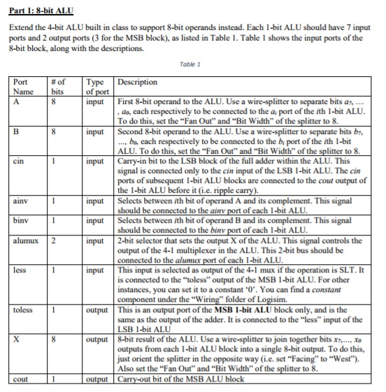
Part 1:8-bit ALU Extend the 4-bit ALU built in class to support 8-bit operands instead. Each 1-bit ALU should have 7 input ports and 2 output ports (3 for the MSB block), as listed in Table 1. Table 1 shows the input ports of the 8-bit block, along with the descriptions. Table 1 Port | # of Type | Description Name bits 0 input First 8-bit operand to the ALU. Use a wire-splitter to separate bits a a7, ao, each respectively to be connected to the a port of the ith 1-bit ALU To do this, set the "Fan Out" and "Bit Width" of the splitter to 8. input Second 8-bit operand to the ALU. Use a wire-splitter to separate bits b bo, each respectively to be connected to the bi port of the ith 1-bit ALU. To do this, set the "Fan Out" and "Bit Width" of the splitter to 8 input | Carry-in bit to the LSB block of the full adder within the ALU-This cin signal is connected only to the cin input of the LSB 1-bit ALU. The cin ports of subsequent 1-bit ALU blocks are connected to the cout output of input Selects between ith bit of operand A and its complement. This signal input Selects between th bit of operand B and its complement. This signal input 2-bit selector that sets the output X of the ALU. This signal controls the ainv binv alumux 2 output of the 4-1 multiplexer in the ALU. This 2-bit bus should be input This input is selected as output of the 4-1 mux if the operation is SLT. It es is connected to the toless" output of the MSB 1-bit ALU. For other instances, you can set it to a constant 0. You can find a constant component under the "Wiring folder of Logisim. toless output This is an output port of the MSB 1-bit ALU block only, and is the same as the output of the adder. It is connected to the "less" input of the LSB 1-bit ALU output 8-bit result of the ALU. Use a wire-splitter to join together bitsx outputs from each -bit ALU block into a single 8-bit output. To do this, just orient the splitter in the opposite way (i.e. set "Facing" to "West" Also set the "Fan Out" and "Bit Width" of the splitter to 8 output Carry-out bit of the MSB ALU block Part 1:8-bit ALU Extend the 4-bit ALU built in class to support 8-bit operands instead. Each 1-bit ALU should have 7 input ports and 2 output ports (3 for the MSB block), as listed in Table 1. Table 1 shows the input ports of the 8-bit block, along with the descriptions. Table 1 Port | # of Type | Description Name bits 0 input First 8-bit operand to the ALU. Use a wire-splitter to separate bits a a7, ao, each respectively to be connected to the a port of the ith 1-bit ALU To do this, set the "Fan Out" and "Bit Width" of the splitter to 8. input Second 8-bit operand to the ALU. Use a wire-splitter to separate bits b bo, each respectively to be connected to the bi port of the ith 1-bit ALU. To do this, set the "Fan Out" and "Bit Width" of the splitter to 8 input | Carry-in bit to the LSB block of the full adder within the ALU-This cin signal is connected only to the cin input of the LSB 1-bit ALU. The cin ports of subsequent 1-bit ALU blocks are connected to the cout output of input Selects between ith bit of operand A and its complement. This signal input Selects between th bit of operand B and its complement. This signal input 2-bit selector that sets the output X of the ALU. This signal controls the ainv binv alumux 2 output of the 4-1 multiplexer in the ALU. This 2-bit bus should be input This input is selected as output of the 4-1 mux if the operation is SLT. It es is connected to the toless" output of the MSB 1-bit ALU. For other instances, you can set it to a constant 0. You can find a constant component under the "Wiring folder of Logisim. toless output This is an output port of the MSB 1-bit ALU block only, and is the same as the output of the adder. It is connected to the "less" input of the LSB 1-bit ALU output 8-bit result of the ALU. Use a wire-splitter to join together bitsx outputs from each -bit ALU block into a single 8-bit output. To do this, just orient the splitter in the opposite way (i.e. set "Facing" to "West" Also set the "Fan Out" and "Bit Width" of the splitter to 8 output Carry-out bit of the MSB ALU block