Answered step by step
Verified Expert Solution
Question
1 Approved Answer
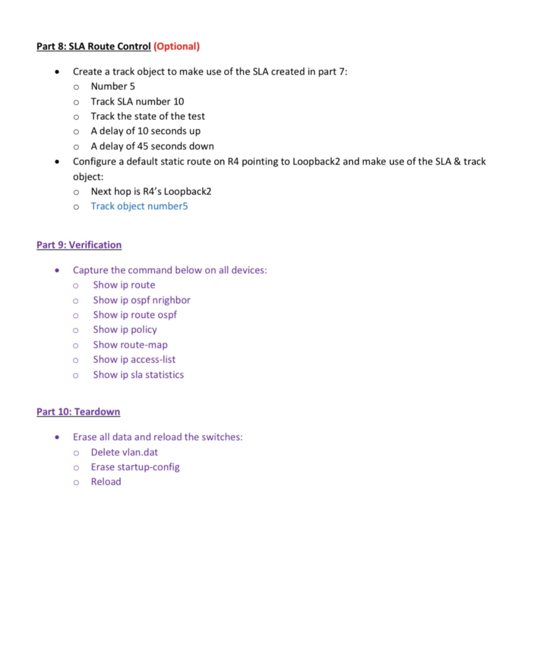
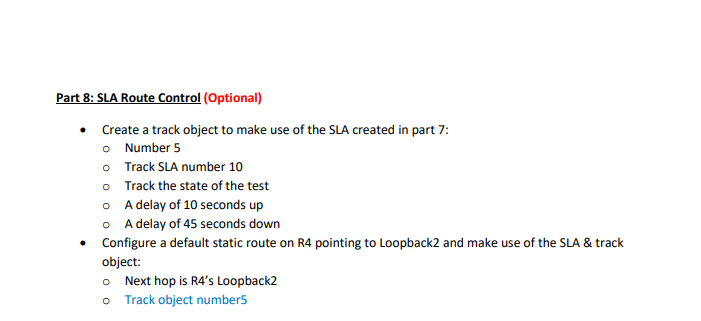
Part 8: SLA Route Control (Optional) Create a track object to make use of the SLA created in part 7: Number 5 0 Track


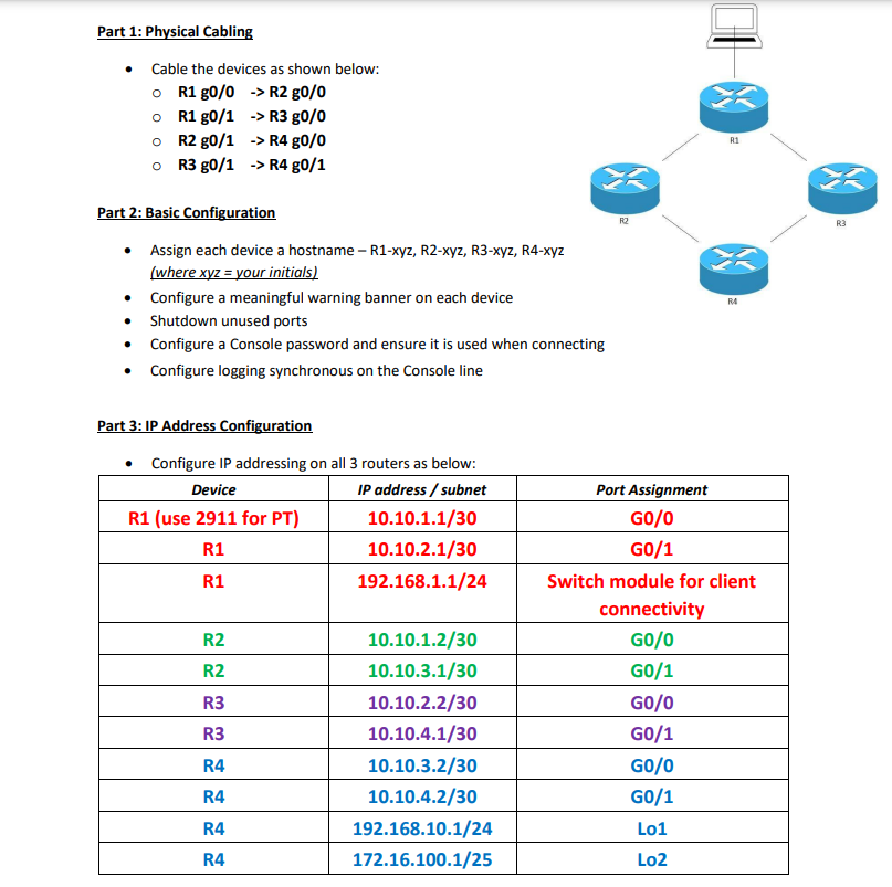
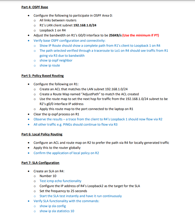
Part 8: SLA Route Control (Optional) Create a track object to make use of the SLA created in part 7: Number 5 0 Track SLA number 10 Track the state of the test A delay of 10 seconds up A delay of 45 seconds down Configure a default static route on R4 pointing to Loopback2 and make use of the SLA & track object: Next hop is R4's Loopback2 0 Track object number5 Part 9: Verification Capture the command below on all devices: Show ip route Show ip ospf nrighbor Show ip route ospf Show ip policy Show route-map Show ip access-list Show ip sla statistics Part 10: Teardown Erase all data and reload the switches: O Delete vlan.dat 0 Erase startup-config Reload Part 1: Physical Cabling Cable the devices as shown below: R1 g0/0 -> R2 g0/0 R1 g0/1 -> R3 g0/0 R2 g0/1 -> R4 g0/0 R3 g0/1 > R4 80/1 Part 2: Basic Configuration Assign each device a hostname - R1-xyz, R2-xyz, R3-xyz, R4-xyz (where xyz = your initials) Configure a meaningful warning banner on each device Shutdown unused ports Configure a Console password and ensure it is used when connecting Configure logging synchronous on the Console line Part 3: IP Address Configuration Configure IP addressing on all 3 routers as below: Device R1 (use 2911 for PT) IP address/subnet Port Assignment GO/0 10.10.1.1/30 R1 R1 10.10.2.1/30 GO/1 192.168.1.1/24 Switch module for client connectivity R2 10.10.1.2/30 GO/0 R2 10.10.3.1/30 GO/1 R3 10.10.2.2/30 GO/O R3 10.10.4.1/30 GO/1 R4 10.10.3.2/30 GO/0 R4 10.10.4.2/30 GO/1 R4 192.168.10.1/24 Lo1 R4 172.16.100.1/25 Lo2 R4 = R3 Part 4: OSPF Base Configure the following to participate in OSPF Area 0: All links between routers R1's LAN client subnet 192.168.1.0/24 Loopback 1 on R4 Adjust the bandwidth on R1's GO/0 interface to be 256KB/s (Use the minimum if PT) Verify base OSPF configuration and connectivity: Show IP Route should show a complete path from R1's client to Loopback 1 on R4 The path selected verified through a traceroute to Lo1 on R4 should see traffic from R1 going via R3 due to bandwidth show ip ospf neighbor show ip route Part 5: Policy Based Routing Configure the following on R1: Create an ACL that matches the LAN subnet 192.168.1.0/24 Create a Route Map named "AdjustPath" to match the ACL created Use the route map to set the next hop for traffic from the 192.168.1.0/24 subnet to be R2's g0/0 interface IP address Apply this route map to the port connected to the laptop on R1 Clear the ip ospf process on R1 Observe the results - a trace from the client to R4's Loopback 1 should now flow via R2 All other traffic e.g. PINGs should continue to flow via R3 Part 6: Local Policy Routing Configure an ACL and route map on R2 to prefer the path via R4 for locally generated traffic Apply this to the router globally Confirm the application of local policy on R2 Part 7: SLA Configuration Create an SLA on R4: Number 10 Test icmp echo functionality Configure the IP address of R4's Loopback2 as the target for the SLA Set the frequency to 25 seconds Start the SLA test instantly and have it run continuously Verify SLA functionality with the commands: show ip sla config show ip sla statistics 10 Part 8: SLA Route Control (Optional) Create a track object to make use of the SLA created in part 7: Number 5 Track SLA number 10 Track the state of the test A delay of 10 seconds up A delay of 45 seconds down Configure a default static route on R4 pointing to Loopback2 and make use of the SLA & track object: Next hop is R4's Loopback2 Track object number5
Step by Step Solution
There are 3 Steps involved in it
Step: 1

Get Instant Access to Expert-Tailored Solutions
See step-by-step solutions with expert insights and AI powered tools for academic success
Step: 2

Step: 3

Ace Your Homework with AI
Get the answers you need in no time with our AI-driven, step-by-step assistance
Get Started


