

Answered step by step
Verified Expert Solution
Question
1 Approved Answer
Part A Part complete Calculate the horizontal component of the resultant force due to F 1 and F 2 . Express your answer to three
Part A
Part complete
Calculate the horizontal component of the resultant force due to F
and F
Express your answer to three significant figures with appropriate units.
View Available Hintsfor Part A
FRx
kN
Previous Answers
Correct
Part B
Part complete
What is the required magnitude for F
Express your answer to three significant figures with appropriate units.
View Available Hintsfor Part B
F
kN
Previous Answers
Correct
Part C
Part complete
Calculate the vertical component of the resultant force.
Express your answer to three significant figures with appropriate units.
View Available Hintsfor Part C
FRy
kN
Previous Answers
Correct
Part D
Part complete
Calculate the magnitude of the resultant force.
Express your answer to three significant figures with appropriate units.
View Available Hintsfor Part D
FR
kN
Previous AnswersView Available Hints
Previous Answers
Correct
Part B
What is the required magnitude for
Express your answer to three significant figures with appropriate units.
View Available Hints
Part C
Calculate the vertical component of the resultant force.
Express your answer to three significant figures with appropriate units.
View Available HintsLearning Goal:
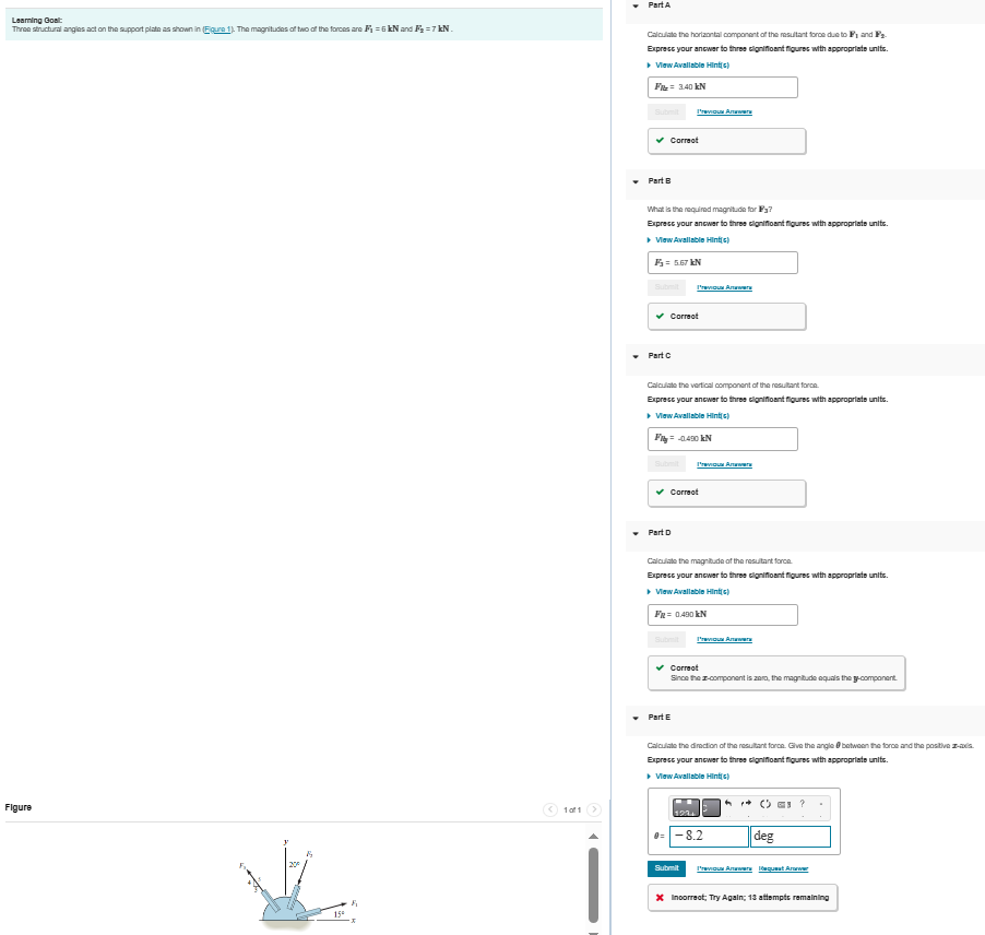
Three structural angles act on the support plate as shown in Figure The magnitudes
of two of the forces are and
Figure
of
Part D
Calculate the magnitude of the resultant force.
Express your answer to three significant figures with appropriate units.
View Available Hints
Correct
Since the component is zero, the magnitude equals the component.
Part E
Calculate the direction of the resultant force. Give the angle between the force and the positive axis.
Express your answer to three significant figures with appropriate units.
View Available Hints
Incorrect; Try Again; attempts remainingLasming Oos:
Three struchural angles act on the support plate as shown in Feure The magnitubles of two of the forces are and
PartA
Calculate the horizantal componont of the masulant force das to and
Expresc your anewar to thres clonifloent flourse with appropriats unite.
Vow Avallable Hintc
Part B
What is the requinad magnitudo for
Euprase your ancwar to thres clonifloant flourse with appropriats unitic.
v Vow Avallable Hintc
correot
Part c
Calculate the vertical component of the reseltant force.
Expresc your ancwar to thros cloniflosit flourse with appropriats unitic.
Vow Avallable Hintc
Irwnoun Antwars
Part D
Calculate the magnibude of the reseftart force.
Eupresc your ancwar to thros clonifloant flourse with appropriats unite.
Vaw Avallable Hintc
Figure
Part E
Calculate the dinaction of the reeultant force. Give the angle betwoen fre force and the postive avla.
Expresc your ancwar to thros clonifloent flourse with appropriats unite.
Vaw Avallable Hintc
Corraot
Since the component is zaro, the magnilude equals the component.
lablo Hints
Inoorreot; Try Again; attempts remaining
Correct
Since the x
component is zero, the magnitude equals the y
component.
Part E
Calculate the direction of the resultant force. Give the angle theta
between the force and the positive x
axis.
Express your answer to three significant figures with appropriate units.
View Available Hintsfor Part E
Activate to select the appropriates template from the following choices. Operate up and down arrow for selection and press enter to choose the input value typeActivate to select the appropriates symbol from the following choices. Operate up and down arrow for selection and press enter to choose the input value type
theta
Previous AnswersRequest Answer
Incorrect; Try Again; attempts remaining
Step by Step Solution
There are 3 Steps involved in it
Step: 1

Get Instant Access to Expert-Tailored Solutions
See step-by-step solutions with expert insights and AI powered tools for academic success
Step: 2

Step: 3
Ace Your Homework with AI
Get the answers you need in no time with our AI-driven, step-by-step assistance
Get Started
Vector Mechanics for Engineers Statics and Dynamics
Authors: Ferdinand Beer, E. Russell Johnston, Jr., Elliot Eisenberg, William Clausen, David Mazurek, Phillip Cornwell
8th Edition
73212229, 978-0073212227