Answered step by step
Verified Expert Solution
Question
1 Approved Answer
Part V: Discharging a Capacitor (PHET Capacitor Lab Basics: Lightbulb): Objective: In this experiment you will study the direction of current flow and time


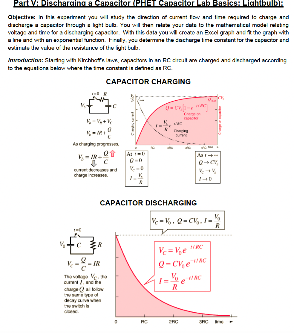
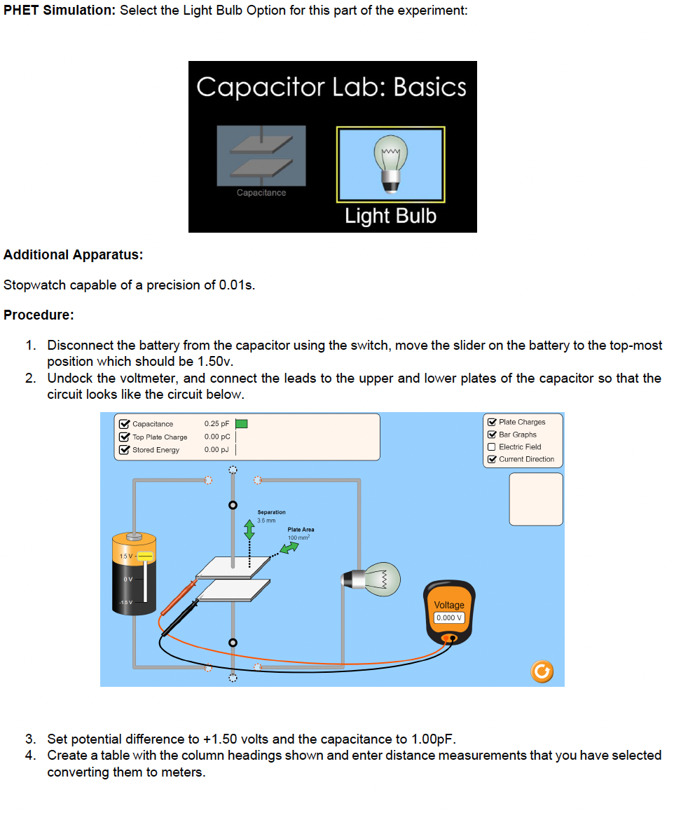
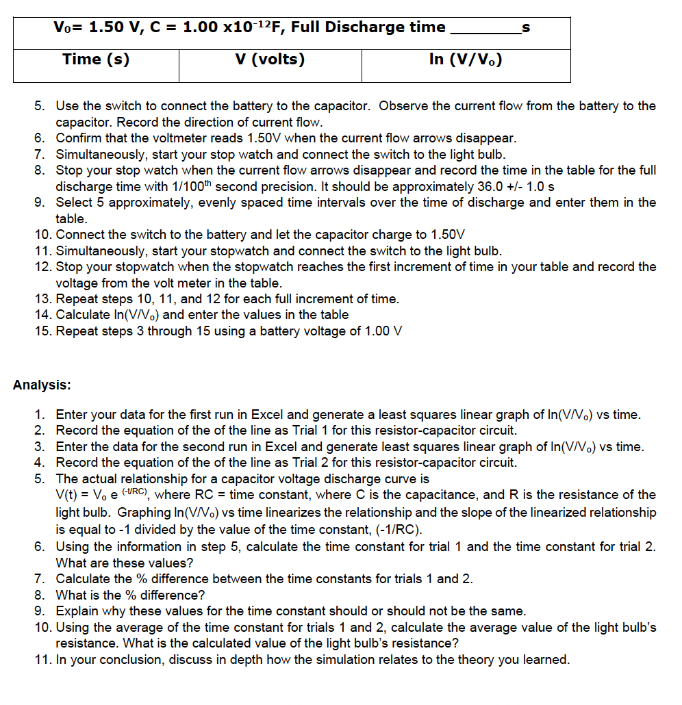
Part V: Discharging a Capacitor (PHET Capacitor Lab Basics: Lightbulb): Objective: In this experiment you will study the direction of current flow and time required to charge and discharge a capacitor through a light bulb. You will then relate your data to the mathematical model relating voltage and time for a discharging capacitor. With this data you will create an Excel graph and fit the graph with a line and with an exponential function. Finally, you determine the discharge time constant for the capacitor and estimate the value of the resistance of the light bulb. Introduction: Starting with Kirchhoff's laws, capacitors in an RC circuit are charged and discharged according to the equations below where the time constant is defined as RC. CAPACITOR CHARGING 1=0 R R Vb =C V = VR+VC V = IR+ As charging progresses, Charging current max 1 = Q=CV,[1-e-/RC] Charge on capacitor R e-1/RC Charging current CV Qmax RC 2RC 3RC 4RC time V = IR+ At t=0 As to C Q=0 current decreases and Vc=0 charge increases. 1 = V Q CV Vc V R 0+1 t=0 R CAPACITOR DISCHARGING Vc=Vo, Q=CV, I=- Vc = = IR The voltage V, the current, and the charge all follow the same type of decay curve when the switch is closed. Vc = Voet/RC Q = CVe-1/RC I = Vo e-t/RC R 0 RC 2RC 3RC time R PHET Simulation: Select the Light Bulb Option for this part of the experiment: Capacitor Lab: Basics Capacitance Light Bulb Additional Apparatus: Stopwatch capable of a precision of 0.01s. Procedure: 1. Disconnect the battery from the capacitor using the switch, move the slider on the battery to the top-most position which should be 1.50v. 2. Undock the voltmeter, and connect the leads to the upper and lower plates of the capacitor so that the circuit looks like the circuit below. Capacitance 0.25 pF Top Plate Charge 0.00 PC Stored Energy 0.00 pJ 15V- -1.5 V Separation 3.6 mm Plate Area 100 mm Voltage 0.000 V Plate Charges Bar Graphs Electric Field Current Direction 3. Set potential difference to +1.50 volts and the capacitance to 1.00pF. 4. Create a table with the column headings shown and enter distance measurements that you have selected converting them to meters. Vo= 1.50 V, C = 1.00 x10⁻¹²F, Full Discharge time Time (s) V (volts) In (V/Vo) 5. Use the switch to connect the battery to the capacitor. Observe the current flow from the battery to the capacitor. Record the direction of current flow. 6. Confirm that the voltmeter reads 1.50V when the current flow arrows disappear. 7. Simultaneously, start your stop watch and connect the switch to the light bulb. 8. Stop your stop watch when the current flow arrows disappear and record the time in the table for the full discharge time with 1/100 th second precision. It should be approximately 36.0 +/- 1.0 s 9. Select 5 approximately, evenly spaced time intervals over the time of discharge and enter them in the table. 10. Connect the switch to the battery and let the capacitor charge to 1.50V 11. Simultaneously, start your stopwatch and connect the switch to the light bulb. 12. Stop your stopwatch when the stopwatch reaches the first increment of time in your table and record the voltage from the volt meter in the table. 13. Repeat steps 10, 11, and 12 for each full increment of time. 14. Calculate In(V/Vo) and enter the values in the table 15. Repeat steps 3 through 15 using a battery voltage of 1.00 V Analysis: 1. Enter your data for the first run in Excel and generate a least squares linear graph of In(V/Vo) vs time. 2. Record the equation of the of the line as Trial 1 for this resistor-capacitor circuit. 3. Enter the data for the second run in Excel and generate least squares linear graph of In(V/Vo) vs time. 4. Record the equation of the of the line as Trial 2 for this resistor-capacitor circuit. 5. The actual relationship for a capacitor voltage discharge curve is V(t) = Voe (RC), where RC = time constant, where C is the capacitance, and R is the resistance of the light bulb. Graphing In(V/Vo) vs time linearizes the relationship and the slope of the linearized relationship is equal to -1 divided by the value of the time constant, (-1/RC). 6. Using the information in step 5, calculate the time constant for trial 1 and the time constant for trial 2. What are these values? 7. Calculate the % difference between the time constants for trials 1 and 2. 8. What is the % difference? 9. Explain why these values for the time constant should or should not be the same. 10. Using the average of the time constant for trials 1 and 2, calculate the average value of the light bulb's resistance. What is the calculated value of the light bulb's resistance? 11. In your conclusion, discuss in depth how the simulation relates to the theory you learned.
Step by Step Solution
There are 3 Steps involved in it
Step: 1

Get Instant Access to Expert-Tailored Solutions
See step-by-step solutions with expert insights and AI powered tools for academic success
Step: 2

Step: 3

Ace Your Homework with AI
Get the answers you need in no time with our AI-driven, step-by-step assistance
Get Started


