

Question: PC+1+ se k or k16 PC+1 Fetch Program Memory Inst Data Out k16 PC+1 SP+1 or SP-1 AR, AR+1 AR-1, or AR+q PC+1 IR DMAR
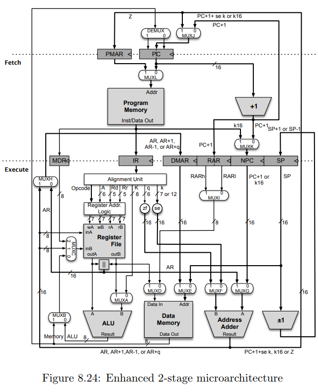

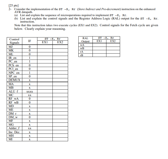
PC+1+ se k or k16 PC+1 Fetch Program Memory Inst Data Out k16 PC+1 SP+1 or SP-1 AR, AR+1 AR-1, or AR+q PC+1 IR DMAR NPC Execute RARI PC+1 or k16 SP Alignment Unit zf (se AR Register File outB AR MUXE Data In Data Memory Address Adder ALU Result Data Out Memory ALU 8 AR, AR+1,AR-1, or AR+q PC+1+se k, k16 or Z Figure 8.24: Enhanced 2-stage microarchitecture DEMUX MJ PCh en PCI en en Fetch ML Addr Program Memory Inst/Data Out MK IR DMAR NPC SP Execute R en PC e SP Control & Alignment Unit 6 /70 12 ister Addr zf (se 16 16 Register File inB Data In MB Data Memory AddresS ALU DM w Adder Inc Result ALU Result Data Out Figure 8.26: Control signals for the enhanced AVR datapath. 25 pts] 2- Consider the implementation of the ST -X, Rr (Store Indirect and Pre-decrement) instruction on the enhanced AVR datapath. (a) List and explain the sequence of microoperations required to implement ST -X, Rr (b) List and explain the control signals and the Register Address Logic (RAL) output for the ST -x, Rr instruction Note that this instruction takes two execute cycles (EX1 and EX2). Control signals for the Fetch cycle are given below. Clearly explain your reasoning. ST -X, Rr EXI ST -X, Rr EXI Control IF 0 0 0 EX2 Signals EX2 WA MK ML IRen PC en PCh en PCI cn NPC en SP en DEMUX MA MB ALU f MC RF wA RF wB MD ME DM r DM w MF MG Adder Inc Dec MH MI rA 0 0 Xx 0 0 0 Xx PC+1+ se k or k16 PC+1 Fetch Program Memory Inst Data Out k16 PC+1 SP+1 or SP-1 AR, AR+1 AR-1, or AR+q PC+1 IR DMAR NPC Execute RARI PC+1 or k16 SP Alignment Unit zf (se AR Register File outB AR MUXE Data In Data Memory Address Adder ALU Result Data Out Memory ALU 8 AR, AR+1,AR-1, or AR+q PC+1+se k, k16 or Z Figure 8.24: Enhanced 2-stage microarchitecture DEMUX MJ PCh en PCI en en Fetch ML Addr Program Memory Inst/Data Out MK IR DMAR NPC SP Execute R en PC e SP Control & Alignment Unit 6 /70 12 ister Addr zf (se 16 16 Register File inB Data In MB Data Memory AddresS ALU DM w Adder Inc Result ALU Result Data Out Figure 8.26: Control signals for the enhanced AVR datapath. 25 pts] 2- Consider the implementation of the ST -X, Rr (Store Indirect and Pre-decrement) instruction on the enhanced AVR datapath. (a) List and explain the sequence of microoperations required to implement ST -X, Rr (b) List and explain the control signals and the Register Address Logic (RAL) output for the ST -x, Rr instruction Note that this instruction takes two execute cycles (EX1 and EX2). Control signals for the Fetch cycle are given below. Clearly explain your reasoning. ST -X, Rr EXI ST -X, Rr EXI Control IF 0 0 0 EX2 Signals EX2 WA MK ML IRen PC en PCh en PCI cn NPC en SP en DEMUX MA MB ALU f MC RF wA RF wB MD ME DM r DM w MF MG Adder Inc Dec MH MI rA 0 0 Xx 0 0 0 Xx
Step by Step Solution
There are 3 Steps involved in it

Get step-by-step solutions from verified subject matter experts