Question
(PLEASE ANSWER ALL 3 QUESTIONS) 1) Assembler a) Activate the following peripherals so that they can be used / configured TIM2 a) Complete the following
(PLEASE ANSWER ALL 3 QUESTIONS)
1) Assembler
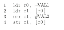
a) Activate the following peripherals so that they can be used / configured TIM2 a) Complete the following program code by replacing the correct values for VAL1 and VAL2.

b) what is the exact technical difference between the two 1dr commands from the code above?
2)
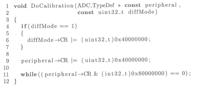
The following calibration function of the ADC is given.

Note The macros / symbols used here are known from the STM library.
a) Describe the purpose of line 11 (please note (b) if necessary)
b) There are four errors in the code shown, which lead to either compiler errors or logic errors (error type: C or L). fill out the following table accordingly.
| row | Type | description |
3)
An existing timer library is to be added. The following functional prototype is given.

With the following description TIM_TypeDef Structure for all registers that are assigned to a timer. pwmMode contains the specific number of the selected PWM mode. pwmChannel contains the specific number of the selected channel.
a) First, only enter the commands that check whether the transferred parameter Timer corresponds to Timers 2 or 1. If this is not the case, a suitable standard value should be used.
b) Now enter the required commands so that the corresponding mode is set correctly. Implement the case for Channel 4.
C) Make each (a) and (b) free of syntax errors. Notice. This only applies to a complete solution of (a) and (b) respectively
1 ldr r0, EVALI 2 ldr rl, [10] ro 3 orr rl, #VAL2 4 4 str rl, (r0] 1 void DoCalibration (ADC-Type Def * const peripheral, 2 const uint32_t diffMode) 3 { 4 if(diffMode == 1) 5 { 6 diffMode+CR = (uint32_t )0x40000000; 7 } 8 9 peripheral CR = (uint32_t )0x40000000; 10 11 while( (peripheral CR & (int32_t ) 0x80000000) = 0); 12 } 1 void ConfigPWMChannel (TIM Type Def const * const timer, 2 const uint8_t pwmMode, 3 const uint8_t pwmChannel); 1 ldr r0, EVALI 2 ldr rl, [10] ro 3 orr rl, #VAL2 4 4 str rl, (r0] 1 void DoCalibration (ADC-Type Def * const peripheral, 2 const uint32_t diffMode) 3 { 4 if(diffMode == 1) 5 { 6 diffMode+CR = (uint32_t )0x40000000; 7 } 8 9 peripheral CR = (uint32_t )0x40000000; 10 11 while( (peripheral CR & (int32_t ) 0x80000000) = 0); 12 } 1 void ConfigPWMChannel (TIM Type Def const * const timer, 2 const uint8_t pwmMode, 3 const uint8_t pwmChannel)
Step by Step Solution
There are 3 Steps involved in it
Step: 1

Get Instant Access to Expert-Tailored Solutions
See step-by-step solutions with expert insights and AI powered tools for academic success
Step: 2

Step: 3

Ace Your Homework with AI
Get the answers you need in no time with our AI-driven, step-by-step assistance
Get Started


