Answered step by step
Verified Expert Solution
Question
1 Approved Answer
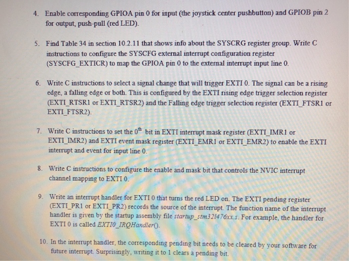
Please answer all Enable corresponding GPIOA pin 0 for input (the joystick center pushbutton) and GPIOB pin 2 for output, push-pull (red LED). 4. Find
Please answer all 
Enable corresponding GPIOA pin 0 for input (the joystick center pushbutton) and GPIOB pin 2 for output, push-pull (red LED). 4. Find Table 34 in section 10.2.11 that shows info about the SYSCRG register group. Write C instructions to configure the SYSCFG external interrupt configuration register (SYSCFG EXTICR) to map the GPIOA pin 0 to the external interrupt input line 0 5. 6. Write C instructions to select a signal change that will trigger EXTI 0. The signal can be a rising edge, a falling edge or both. This is configured by the EXTI rising edge trigger selection register (EXTI RTSR1 or EXTI RTSR2) and the Falling edge trigger selection register (EXTI FTSR1 or EXTI FTSR2) 7. Write C instructions to set the o* bit in EXTI interrupt mask register (EXTI IMR1 or EXTI IMR2) and EXTI event mask register (EXTI EMR1 or EXTI EMR2) to enable the EXTI interrupt and event for input line 0 Write C instructions to configure the enable and mask bit that controls the NVIC interrupt channel mapping to EXTI 0 8. 9. Write an interrupt handler for EXTI 0 that turns the red LED on. The EXTI pending register EXTI PRI or EXTI PR2) records the source of the interrupt. The function name of the interrupt handler is given by the startup assembly file startup_stm321476xs. For example, the handler for EXTI 0 is called EXTI0 IRQHandlerO 10. In the interrupt handler, the corresponding pending bit needs to be cleared by your software for future interrupt. Surprisingly, writing it to 1 clears a pending bit. Enable corresponding GPIOA pin 0 for input (the joystick center pushbutton) and GPIOB pin 2 for output, push-pull (red LED). 4. Find Table 34 in section 10.2.11 that shows info about the SYSCRG register group. Write C instructions to configure the SYSCFG external interrupt configuration register (SYSCFG EXTICR) to map the GPIOA pin 0 to the external interrupt input line 0 5. 6. Write C instructions to select a signal change that will trigger EXTI 0. The signal can be a rising edge, a falling edge or both. This is configured by the EXTI rising edge trigger selection register (EXTI RTSR1 or EXTI RTSR2) and the Falling edge trigger selection register (EXTI FTSR1 or EXTI FTSR2) 7. Write C instructions to set the o* bit in EXTI interrupt mask register (EXTI IMR1 or EXTI IMR2) and EXTI event mask register (EXTI EMR1 or EXTI EMR2) to enable the EXTI interrupt and event for input line 0 Write C instructions to configure the enable and mask bit that controls the NVIC interrupt channel mapping to EXTI 0 8. 9. Write an interrupt handler for EXTI 0 that turns the red LED on. The EXTI pending register EXTI PRI or EXTI PR2) records the source of the interrupt. The function name of the interrupt handler is given by the startup assembly file startup_stm321476xs. For example, the handler for EXTI 0 is called EXTI0 IRQHandlerO 10. In the interrupt handler, the corresponding pending bit needs to be cleared by your software for future interrupt. Surprisingly, writing it to 1 clears a pending bit
Step by Step Solution
There are 3 Steps involved in it
Step: 1

Get Instant Access to Expert-Tailored Solutions
See step-by-step solutions with expert insights and AI powered tools for academic success
Step: 2

Step: 3

Ace Your Homework with AI
Get the answers you need in no time with our AI-driven, step-by-step assistance
Get Started


