

Question: Please answer and explain Interference INTRODUCTION As long ago as the 17111 century, there were two competing models to describe the nature of light. Isaac
Please answer and explain
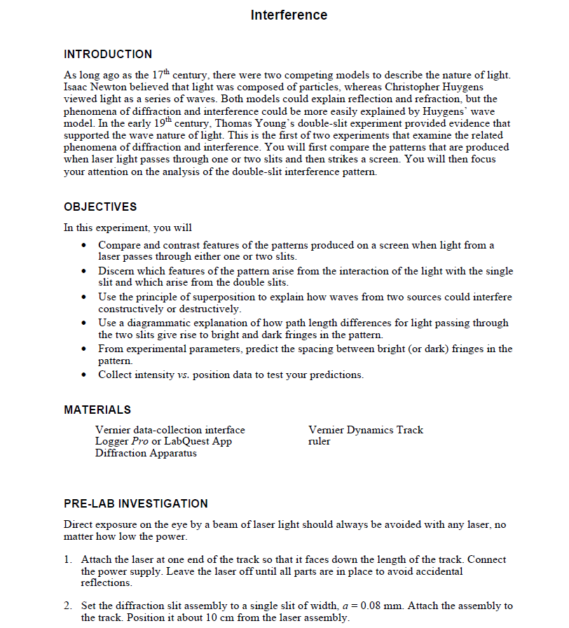
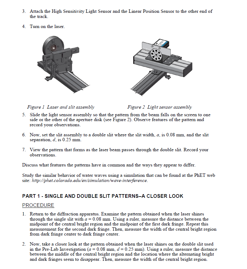
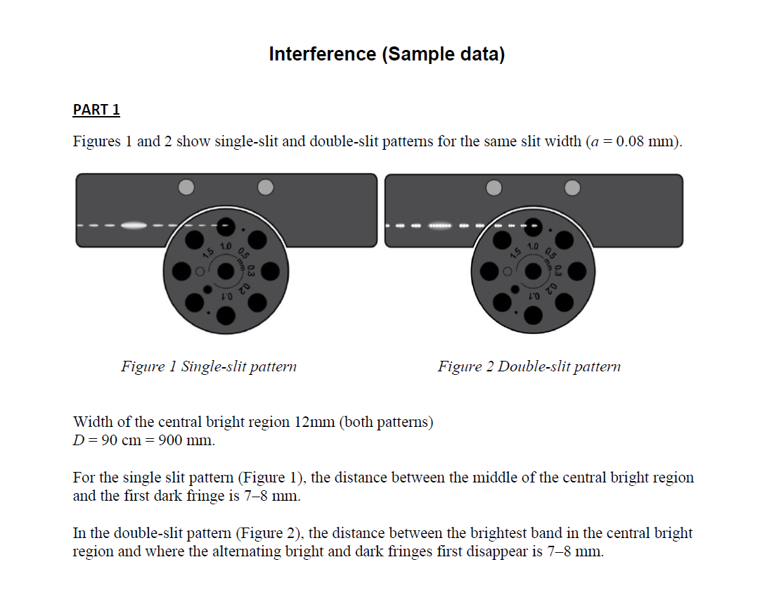
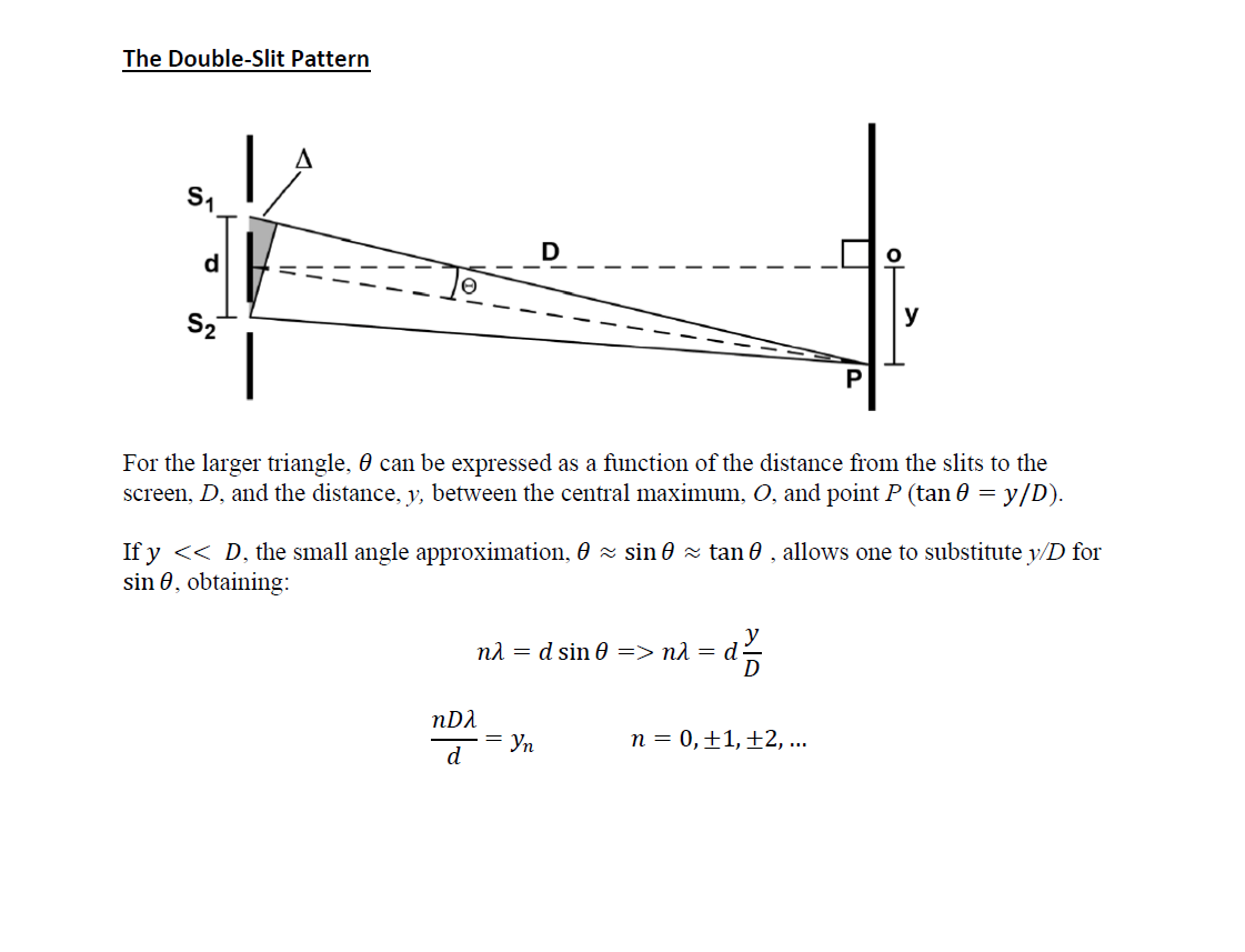
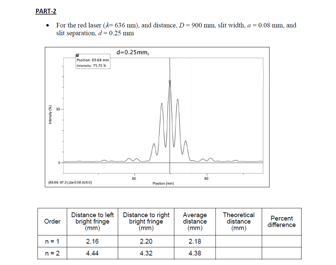
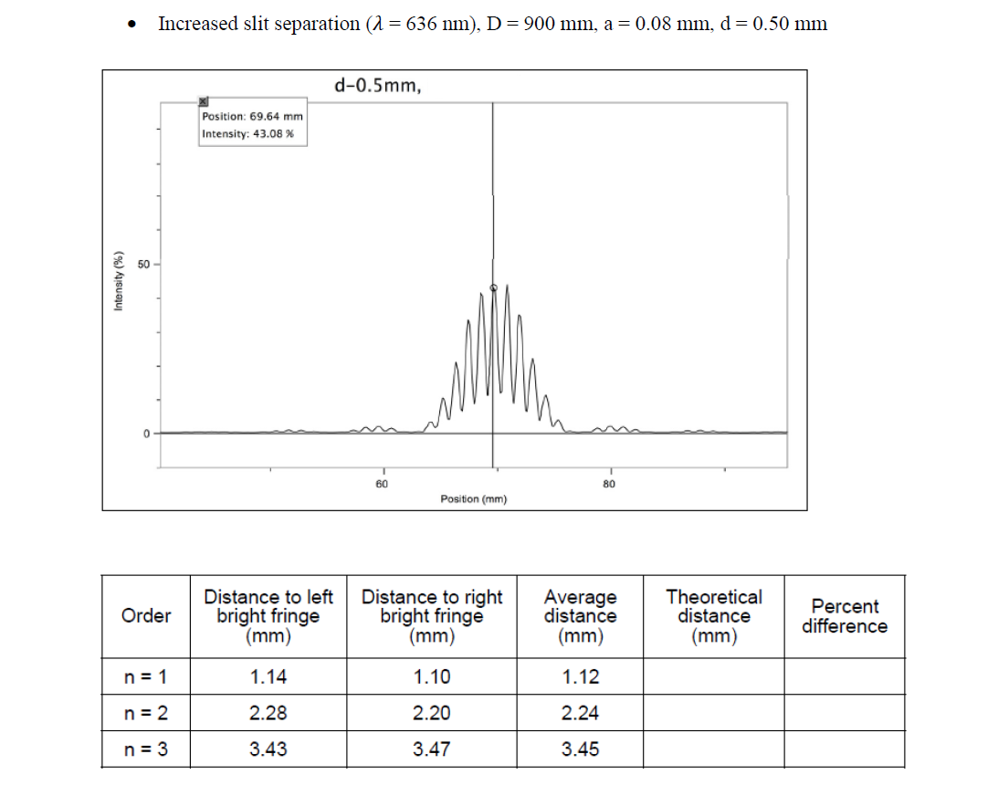
Interference INTRODUCTION As long ago as the 17111 century, there were two competing models to describe the nature of light. Isaac Newton believed that light was composed of particles, whereas Christopher Huygens viewed light as a series of waves. Both models could explain reection and refraction, but the phenomena of diffraction and interference could be more easily explained by Huygens' wave model. In the early 1'51"tll century, Thomas Young's doubleslit experiment provided evidence that supported the wave nature of light. This is the rst of two experiments that examine the related phenomena of diffraction and interference. You will rst compare the patterns that are produced when laser light passes through one or two slits and then strikes a screen. You will then focus your attention on the analysis of the doubleslit interference pattern. OBJECTIVES In this experiment, you will 0 Compare and contrast features of the patterns produced on a screen when light from a laser passes through either one or two slits. 0 Discern which features of the pattern arise from the interaction of the light with the single slit and which arise om the double slits. 0 Use the principle of superposition to explain how waves from two sources could interfere constructively or destructively. C Use a diagrammatic explanation of how path length differences for light passing through the two slits give rise to bright and dark fringes in the pattern. 0 From experimental parameters, predict the spacing between bright (or dark) fringes in the pattern. 0 Collect intensity vs. position data to test your predictions. MATERIALS Vernier datacollection interface Vernier Dynamics Track Logger Pro or LahQuest App ruler Diffraction Apparatus FEE-LAB INVESTIGATION Direct exposure on the eye by a beam of laser light should always be avoided with any laser, no matter how low the power. 1. Attach the laser at one end of the track so that it faces down the length of the track. Connect the power supply. Leave the laser off until all pans are in place to avoid accidental reections. 2. Set the dif'action slit assembly to a single slit of width= a = 0.08 mm. Attach the assembly to the track. Position it about 10 em 'om the laser assembly. 3. Attach the High Sensitivity Light Sensor and the Linear Position Sensor to the other end of the track. 4. Turn on the laser. Figure 1 Laser and sift arsmbb; F igure 2 Light sensor 1:532:11be 5. Slide the light sensor assembly so that the pattern om the beam falls on the screen to one side or the other of the aperture disk (see Figure 2). Observe features of the pattern and record your observations. Now= set the slit assembly to a double slit where the slit width, 0. is 0.03 mm, and the slit separation, :17, is 0.25 mm. View the pattern that forms as the laser beam passes through the double slit. Record your observations. Discuss what features the patterns have in common and the ways they appear to di'er. Study the similar behavior of water waves using a simulation that can be found at the PhET web site: Fin}!rfr'phetofomdo.edufenfsimufaonmveinferzrence. FART1 - SINGLE AND DOUBLE SLIT PATTERNS-A CLOSER LOOK PROCEDURE 1. Return to the diaction apparatus. Examine the pattern obtained when the laser shines through the single slit with a = E mm. Using a ruler, measure the distance between the midpoint of the central bright region and the midpoint of the rst dark fringe. Repeat this measurement for the second dark fringe. Then= measure the width of the central bright region from dark fringe center to dark fringe center. Now, take a closer look at the pattern obtained when the laser shines on the double slit used in the PreLab Investigation {:1 = CLUE mm d = 0.25 mm). Using a ruler, measure the distance between the middle of the central bright region and the location where the alternating bright and dark fringes seem to disappear. Then= measure the width of the central bright region. EVALUATION OF DATA 1. Compare your measurements for the single and doublesht patterns. 1What feature of the pattern appears to arise from the single slit? 'What feature appears to arise from the double slit? PART 2 - INTERFERENCE AND THE DOUBLE-SLIT PATTERN Refer to your text or lecture notes to compare its explanation of the doubleslit interference into your observations. Determine how the superposition of waves can give rise to either constructive or destructive interference. Show that the small angle approximation allows you to substitute will for sin E'in your calculation of 'inge spacing. 1What variables affect the spacing of the bright fringes in the doubleslit pattern?I PROCEDURE 1. Turn on the laser and start the datacollection program. 2. Record the distance, D, from the slit assembly to the light sensor. Record the slit width, at, and the slit separation, 13', for the double-slit conguration you used in Part 1, as well as the wavelength, 13., of the laser. 3. Move the sensor assembly all the way to the right as viewed from the laser. Zero both 516115015. 4. Start data collection, and then move the sensor assembly stage toward the other side of the rail on which it is mounted. Take at least 2'!) seconds to execute the motion. Stop collecting data when the stage reaches the end stop. 5. Choose a doubleslit conguration in which you change either the slit width or the slit separation, then repeat the previous step. EVALUATION OF DATA 1. From the values of D, d and .l, calculate the theoretical distance ya, for the rst three maxima to either side of the central maximum for your first trial. 2. View the intensity vs. position graph for your rst trial. Zoom in on the portion of the graph that shows the most useful information. Record the peak position. Find the positions of the first two bright fringes on either side. Explain why you have difculty nding the n = 3 bright fringe. 3. Determine the distance, y\Interference (Sample data) PART 1 Figures 1 and 2 show single-slit and double-slit patterns for the same slit width (a = 0.08 mm). 1.0 1.0 0.5 LO Figure 1 Single-slit pattern Figure 2 Double-slit pattern Width of the central bright region 12mm (both patterns) D = 90 cm = 900 mm. For the single slit pattern (Figure 1), the distance between the middle of the central bright region and the first dark fringe is 7-8 mm. In the double-slit pattern (Figure 2), the distance between the brightest band in the central bright region and where the alternating bright and dark fringes first disappear is 7-8 mm.The Double-Slit Pattern IA 51/ For the larger triangle, 6 can be expressed as a function of the distance from the slits to the screen, D, and the distance, y, between the central maximum, 0, and point P (tan 9 = y / D). If y ml=d% RDA 7:)?\" H : 0,i1,i2,... PART-2 . For the red laser (1=636 nm), and distance, D = 900 mm, slit width, a = 0.08 mm, and slit separation, d = 0.25 mm d=0.25mm, Position: 69.68 mm Intensity: 75.72 % 50 Intensity (%) 60 80 (69.69, 97.2) (Ax:0.08 41:0.0) Position (mm) Distance to left Distance to right Average Theoretical Order distance Percent bright fringe bright fringe distance (mm) difference (mm) (mm) (mm) n = 1 2.16 2.20 2.18 n = 2 4.44 4.32 4.380 Increased slit separation (11 = 636 11111), D = 900 mm, a = 0.08 mm, d = 0.50 mm Pnsluon: 59'\" mm Intensity: 43.08 9' d0.5mm, Distance to left Distance to right Theoretical bright fringe bright fringe distance (mm) (mm) Percent difference
Step by Step Solution
There are 3 Steps involved in it

Get step-by-step solutions from verified subject matter experts