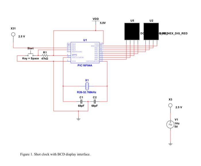
Please answer by showing necessary code and its modifications.
In this exercise you will study an alternative display for the basketball shot clock. Multisim includes in its parts library a BCD seven-segment display that requires only four data lines to display all 10 decimal digits. Recall that BCD (binary-coded decimal) is a means of representing individual decimal digits using their binary equivalent in a four-bit word known as a nibble. Two BCD digits can be driven directly from Port B of the processor, vastly simplifying the display wiring and the coding of the shot clock. B. CIRCUIT CONSTRUCTION 1. Make a new folder for this exercise. 2. Launch Multisim and save the diagram in the exercise folder. 3. Copy your original shot clock diagram to the new Multisim diagram. 4. When prompted by the code wizard, create new workspace and project folders in the exercise folder. 5. Modify the circuit as shown in Figure 1. The displays are DCD_HEX_DIGIT_RED parts from the HEX DISPLAY family of the Indicators group. Note that the data lines to these displays are not marked, but the leftmost line of each is the most-significant bit while the rightmost line is the least-significant. C. PROGRAMMING 1. Copy your original shot clock program into the new project folder, renaming it appropriately, and use the code manager to attach it to your project. 2. Modify subroutine "scan" to drive the two BCD displays. Hint 1: The values retumed by subroutine "div 8 " for the one's and ten's digits are binary-coded decimals because they fit into a four-bit (one nibble) representation. Hint 2: You will have to find a way to combine the BCD values for the two digits into a single byte that can be written to Port B. The nibble for the ten's digit, which originally occupies bits 0 through 3, will need to end up in bits 4 through 7 of the output byte. Hint 3: You will need to do some reading in the PIC data sheet with emphasis on the instruction "swapf." Figure 1. Shot clock with BCD display interface